Power supply management device and method for battery

A technology for power supply management and batteries, applied in battery circuit devices, circuit devices, primary battery use/maintenance, etc., can solve problems such as difficult to accurately detect batteries, achieve accuracy and flexibility, ensure good work, and prolong service life Effect

Inactive Publication Date: 2009-04-29
SHENZHEN MINDRAY BIO MEDICAL ELECTRONICS CO LTD
View PDF0 Cites 47 Cited by
  • Summary
  • Abstract
  • Description
  • Claims
  • Application Information

AI Technical Summary

Problems solved by technology

[0006] It can be seen that the battery voltage is greatly affected by factors such as the environment, making it difficult to accurately detect the remaining battery power based on the battery voltage. Discharge, there is a greater risk to the normal operation of the device, and it cannot be guaranteed that the accurate battery power supply state transition will be achieved within the entire service life of the battery

Method used


Image

  • Power supply management device and method for battery
  • Power supply management device and method for battery
  • Power supply management device and method for battery

Examples


Embodiment 1

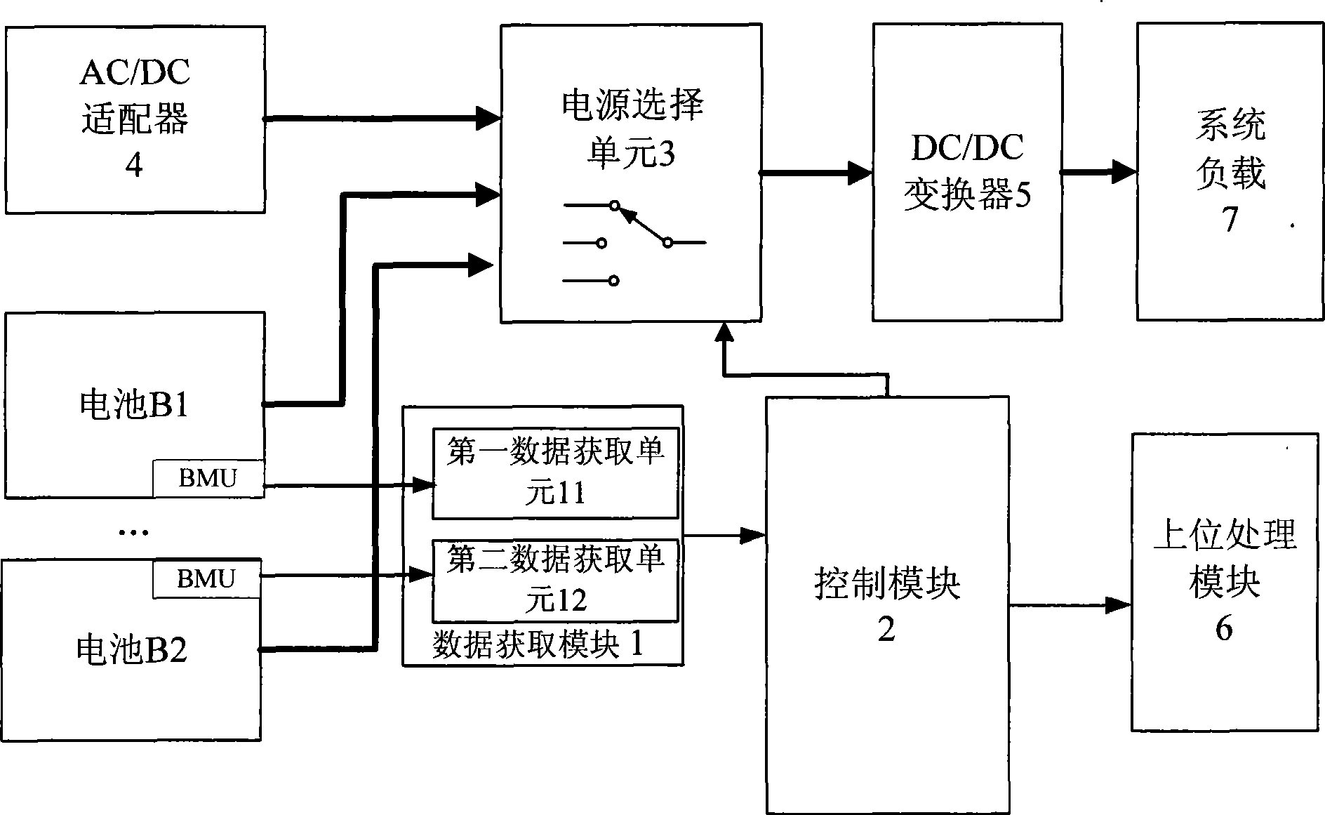
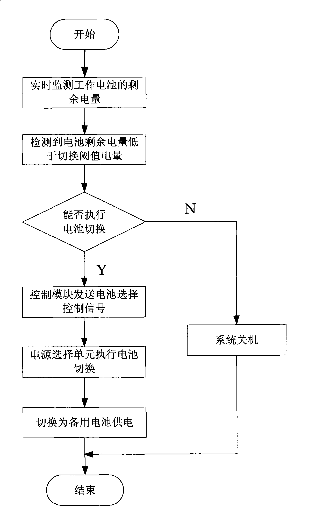
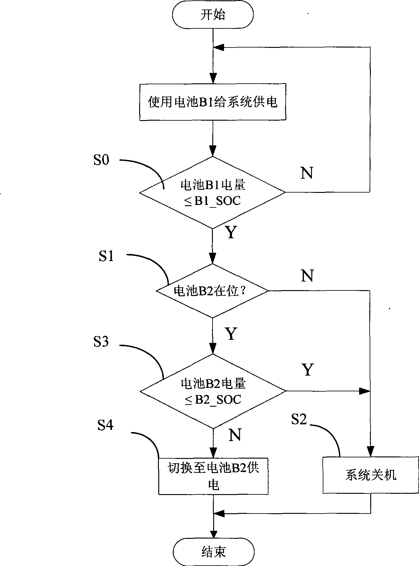
[0041] Such as figure 1As shown, the battery power supply management device includes a data acquisition module 1 , a control module 2 , and a power supply selection unit 3 . The output end of the battery power is coupled to the DC / DC converter 5 through the power selection unit 3 , and the output end of the DC / DC converter 5 is coupled to the system load 7 . The equipment used in this embodiment is powered by a smart battery, and the smart battery has a battery management unit (BMU) (Battery Management Unit), which can obtain status data such as the remaining battery power and the number of charging cycles and store them in its memory. The data acquisition module 1 is connected with the battery management unit BMU through the SMBus (system management serial bus), reads the remaining battery power in the battery management unit BMU, and sends it to the control module 2, and the control module 2 outputs control according to the remaining battery power. signal, and the power sup...

Embodiment 2

[0059] Such as Figure 4 As shown, the difference between this embodiment and the first embodiment is that the threshold correction module 8 is added, and the threshold correction module 8 corrects the switching threshold power and provides it to the control module 2 . The threshold correction module 8 further includes a parameter acquisition unit, a correction coefficient calculation unit and a threshold calculation unit. Wherein, the parameter acquisition unit at least obtains the number of battery charge and discharge cycles from the battery management unit BMU of the smart battery, the correction coefficient calculation unit calculates the correction coefficient according to the number of battery charge and discharge cycles, the threshold value calculation unit multiplies the correction coefficient and the switching threshold electric quantity, and the product as the corrected switching threshold power. The above correction factor is calculated according to the following ...


PUM


Abstract

The invention discloses a battery powered managing device and is suitable for a battery powered apparatus. The device comprises a data acquisition module which comprises a first data acquisition unit for acquiring state data of a battery which is in a power supplying state, the battery is an intelligent battery, the state data at least comprises a remaining electrical quantity value, a control module which is used for comparing the remaining electrical quantity value with a switching threshold value of the battery, and when the remaining electrical quantity value is less than the switching threshold value of the electrical quantity, the battery is controlled to end the power supplying. The invention further discloses a battery powered managing method, and when the remaining electrical quantity value is less than the switching threshold value of the electrical quantity, the battery is controlled to be stopped supplying. The battery powered managing device and the method can ensure that the battery powered state can be accurately and timely switched in the running process of the equipment.

Description

【Technical field】 [0001] The invention relates to the field of battery power supply management, in particular to a battery power supply management device and method. 【Background technique】 [0002] The normal operation of electronic equipment often has high requirements for the power supply management of the equipment. In the field of medical electronic equipment, this requirement is even more stringent. For example, portable defibrillation monitors are often used for first aid outside the hospital, and need to provide high-energy defibrillation current and monitoring functions. Therefore, in addition to the AC / DC adapter as the power supply, the defibrillation monitor is also equipped with a large-capacity power supply Battery. And in the process of implementing first aid, the defibrillation monitor usually uses a battery as the main power supply. Therefore, it is very important to ensure the normal use of the battery, especially when the battery capacity is not allowed ...

Claims


Application Information

Patent Timeline
Patent Type & Authority Applications(China)
IPC IPC(8): H01M6/50H01M10/42G06F19/00G06Q10/00G06Q90/00H02J7/00
CPCY02E60/12Y02E60/10
Inventor 李光季百苗刘方张皖滕大志安敏
Owner SHENZHEN MINDRAY BIO MEDICAL ELECTRONICS CO LTD
Why Eureka
Try Eureka