
Endoscope device

An endoscope and narrow-band technology, applied in the field of endoscope devices, can solve problems such as the useless burden on the surgeon and the mental stress of the examinee

Active Publication Date: 2009-04-29
OLYMPUS CORP
View PDF2 Cites 18 Cited by
  • Summary
  • Abstract
  • Description
  • Claims
  • Application Information

AI Technical Summary

Problems solved by technology

As a result, the endoscope device proposed in Japanese Patent Application Laid-Open No. 2002-095635 has the following problem: in the case of observing with narrow-band light, for example, it is necessary to conduct and suspect a lesion while observing an image of, for example, residue, bile, or intestinal fluid. The image of the bleeding site is roughly the same while observing it, which puts a useless burden on the surgeon
In addition, the endoscope device proposed in Japanese Patent Laying-Open No. 2002-095635 also has the following problems: in the case of narrow-band light observation, images of residues, bile, or intestinal juice are displayed on a display unit such as a monitor, As a red image that is almost the same color as blood, it causes mental stress to the subject

Method used


Image

  • Endoscope device
  • Endoscope device
  • Endoscope device

Examples


no. 1 Embodiment approach

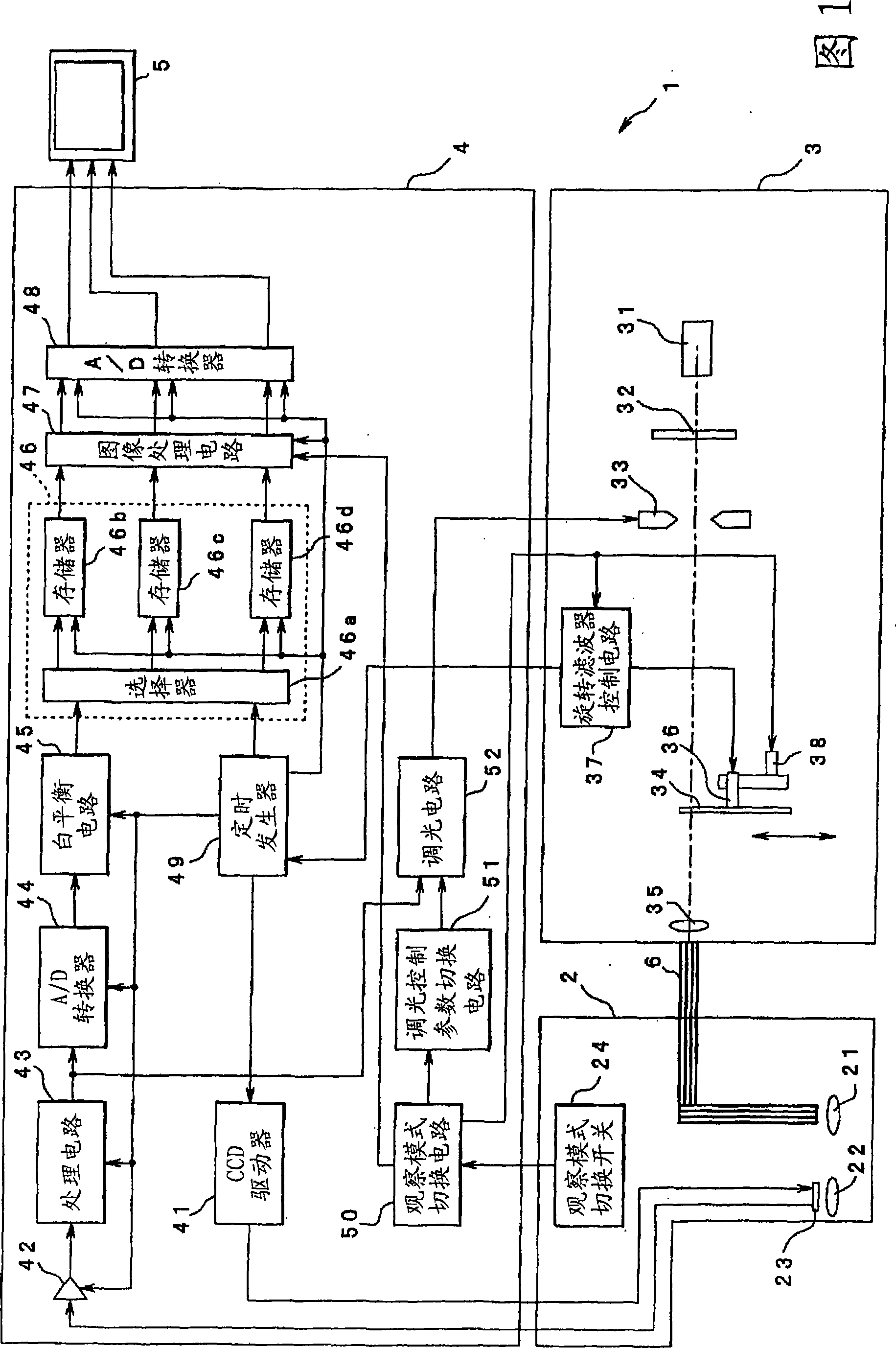
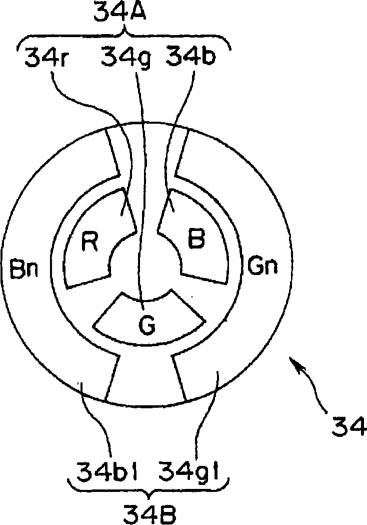
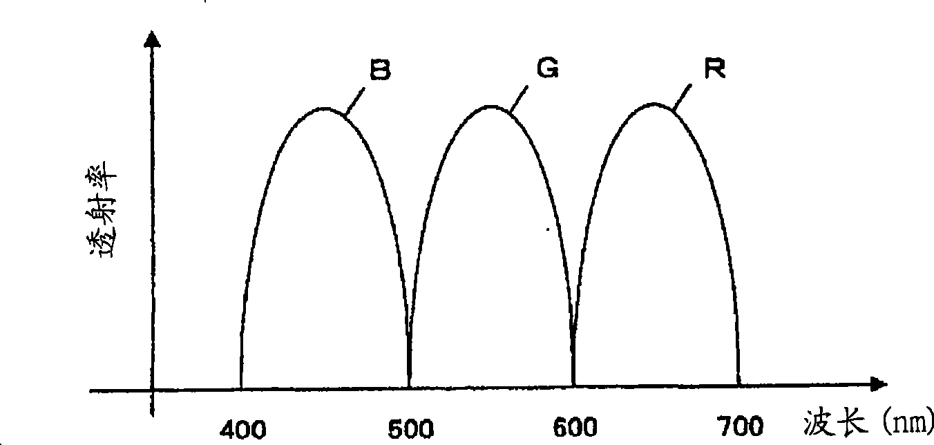
[0053] Figure 1~ Figure 6 It relates to the first embodiment of the present invention. FIG. 1 is a diagram showing an example of the configuration of a main part of an endoscope apparatus according to a first embodiment. figure 2 It is a diagram showing an example of the configuration of the rotary filter in the endoscope apparatus of FIG. 1 . image 3 is showing figure 2 A graph showing an example of the transmission characteristics of each filter included in the first filter bank in the rotation filter. Figure 4 is showing figure 2 A graph showing an example of the transmission characteristics of each filter included in the second filter bank in the rotation filter. Figure 5 It is a diagram showing an example of the configuration of an image processing circuit in the endoscope apparatus of FIG. 1 . Figure 6 It is a diagram showing an example of an image of a subject in the narrow-band light observation mode obtained by observation using the endoscope apparatus of FI...

no. 2 Embodiment approach

[0124] Figure 7~ Figure 9 It relates to the second embodiment of the present invention. 7 is a diagram showing an example of the configuration of a main part of an endoscope apparatus according to a second embodiment. Figure 8 It is a graph showing an example of the spectral characteristics of the narrowband filter included in the endoscope device according to the second embodiment. Figure 9 It is a diagram showing an arrangement example of each filter used in the color separation filter included in the endoscope apparatus according to the second embodiment.

[0125] In addition, in the following description, the detailed description of the part which has the same structure as that of 1st Embodiment is abbreviate|omitted.

[0126] As shown in FIG. 7 , an endoscope device 201 according to the second embodiment includes, as main parts, an electronic endoscope (hereinafter simply referred to as an endoscope) 202 which is inserted into a body cavity or the like to perform end...


PUM

PropertyMeasurementUnit
Center wavelengthaaaaaaaaaa

Abstract

An endoscope device is comprised of an illuminating means for projecting first narrow band light with a wavelength band of a blue region and second narrow band light with a wavelength band of a green region to an object in a living body, a photographing means for photographing a first object image in the case that the object is illuminated by the first narrow band light and a second object image in the case that the object is illuminated by the second narrow band light, a memory means for storing the first object image as green and blue components and the second object image as red and blue components, a hue converting means for carrying out prescribed color conversion processing for the red, green and blue components so as to make an image of a prescribed object an image of a prescribed first color other than red.

Description

technical field [0001] The present invention relates to an endoscope device, and more particularly to an endoscope device capable of observing inside a living body based on narrow-band light. Background technique [0002] Conventionally, an endoscope device including an endoscope, a light source device, and the like has been widely used in the medical field and the like. In particular, endoscopic devices in the medical field are mainly used for the observation of living bodies by surgeons and the like. [0003] In addition, as a generally known method of observation using an endoscope device in the medical field, for example, in addition to normal observation, there is also narrow-band light observation (NBI: Narrow Band Imaging). The subject is irradiated with white light, and an image of the subject that is approximately the same as observed with the naked eye can be obtained. In this narrow-band light observation, the subject is irradiated with a frequency band narrower ...

Claims


Application Information

Patent Timeline
IPC IPC(8): A61B1/04A61B1/00A61B1/06G02B23/24H04N7/18
CPCG02B23/26G02B23/2469A61B1/00009A61B1/0005G02B21/365G02B26/008A61B1/0653A61B1/0638G02B23/2484A61B1/063A61B1/0646A61B1/0655A61B1/04H04N7/18
Inventor 五十岚诚山崎健二
Owner OLYMPUS CORP
Learn More