Wall panel

A technology of wall panels and folding panels, which is applied in the direction of walls, building components, buildings, etc., can solve the problems of high transmission efficiency, high transportation costs, decreased stress transmission efficiency, and increased cost of wall panels, achieving reliable screw fixing and preventing Excellent resistance to deterioration and deformability

Active Publication Date: 2009-04-29
NIPPON STEEL CORP
View PDF5 Cites 5 Cited by
  • Summary
  • Abstract
  • Description
  • Claims
  • Application Information

AI Technical Summary

Problems solved by technology

[0010] In the conventional technique of (1) above, since a plurality of horizontal bars are used, there is a problem that the number of parts increases and the production cost of the panel increases.
[0011] In the conventional technique of (2) above, since the volume increases when the face materials are stacked, it is not possible to transport multiple face materials
As a result, the transportation efficiency decreases and the transportation cost increases, so the cost of the wall panel increases, and there is an out-of-plane bending part of the steel plate in the stress transmission path from the frame to the surface material, so the stress transmission efficiency may decrease. question

Method used


Image

  • Wall panel
  • Wall panel
  • Wall panel

Examples


Embodiment Construction

[0101] Each embodiment of the present invention will be described below based on the drawings.

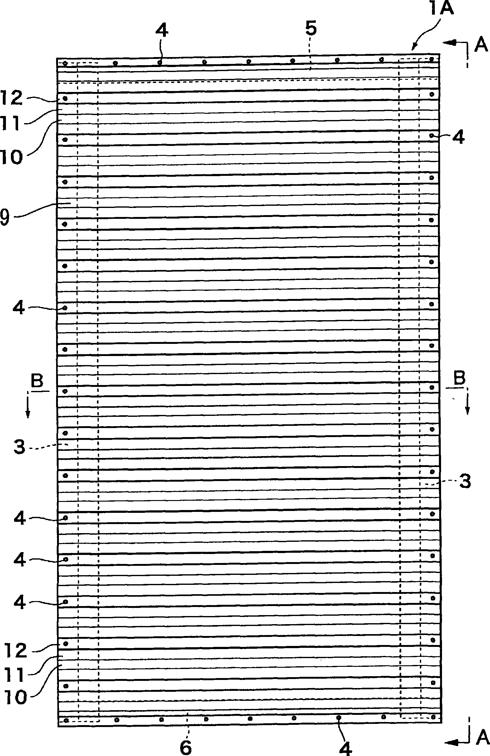
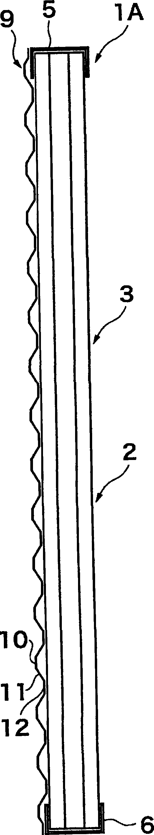
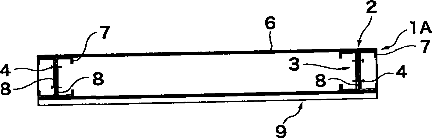
[0102] First, the frame body 2 used for wall panel 1A, 1B, 1C of each embodiment is demonstrated. Such as Figure 5A ~ Figure 5C As shown, the rectangular frame body 2 is composed of a pair of vertical frame members 3 arranged opposite to each other at intervals, arranged astride the upper ends of these vertical frame members 3, and fastening members 4 are fixed by screws such as self-tapping screws. The joined upper horizontal frame members 5 and the lower horizontal frame members 6 arranged across the lower ends of these vertical frame members 3 and joined by screw fixing fixtures 4 such as self-tapping screws are configured. No reinforcement bars are provided between the vertical frame members 3 . In each embodiment, the folded plates described later exert the same function as when the reinforcement bars are provided, thereby preventing the vertical frame members 3 from twistin...


PUM


Abstract

A wall panel comprises a frame body having vertical frame members and lateral frame members and surface members fixed to the frame body by screws. Each surface member is made of a thin folded plate, and fixed to at least one surface of the frame body.

Description

technical field [0001] The present invention relates to a wall panel used as a load-bearing wall in a building such as a steel structure house. [0002] This application is based on Japanese Patent Application No. 2006-109117 and Japanese Patent Application No. 2007-099537, and uses the contents thereof. Background technique [0003] As conventional load-bearing walls, there are, for example, structures disclosed in the following (1) to (3). [0004] (1) if Figure 6 As shown, in order to prevent bending or torsional deformation of the vertical frame material 3, a plurality of horizontal bars 22 are arranged in parallel at intervals in the vertical direction so as to be accommodated in the frame body 2, and then the surface material (not shown) is installed. Shown) of the load-bearing wall (for example, refer to Patent Document 1). In addition, the length of the vertical frame material 3 is about 3 m which is the height of the first floor of a building. [0005] (2) It is...

Claims


Application Information

Patent Timeline
Patent Type & Authority Applications(China)
IPC IPC(8): E04B2/56E04C2/32
CPCE04C2/384E04C2/322
Inventor 田中浩史河合良道
Owner NIPPON STEEL CORP
Why Eureka
Try Eureka