Composite desulfuration dust removing device
A kind of desulfurization and dust removal equipment, compound technology, applied in the field of flue gas desulfurization and dust removal equipment, can solve the problems of low desulfurization and dust removal index, insignificant efficiency improvement, no change, etc., achieve good desulfurization and dust removal effect, and improve desulfurization and dust removal efficiency
Inactive Publication Date: 2010-12-01
HUNAN JIAYU ENVIRONMENT PROTECTION EQUIP
View PDF0 Cites 0 Cited by
- Summary
- Abstract
- Description
- Claims
- Application Information
AI Technical Summary
Problems solved by technology
The current desulfurization and dust removal equipment is generally composed of one tower or more than one tower in parallel. The dust removal efficiency of this kind of dust removal equipment is relatively low and the cost is relatively high. Although people have made many small improvements to improve its efficiency, the basic structure remains the same. No change, each tower still has pneumatic spraying device, flue gas dehydration device, dry section area
Therefore, the efficiency improvement is not significant, and the achieved desulfurization and dust removal index is relatively low
Method used
View moreImage
Smart ImageViewing Examples
Examples
Embodiment Construction
Login to View More PUM
| Property | Measurement | Unit |
|---|---|---|
| dust removal efficiency | aaaaa | aaaaa |
Abstract
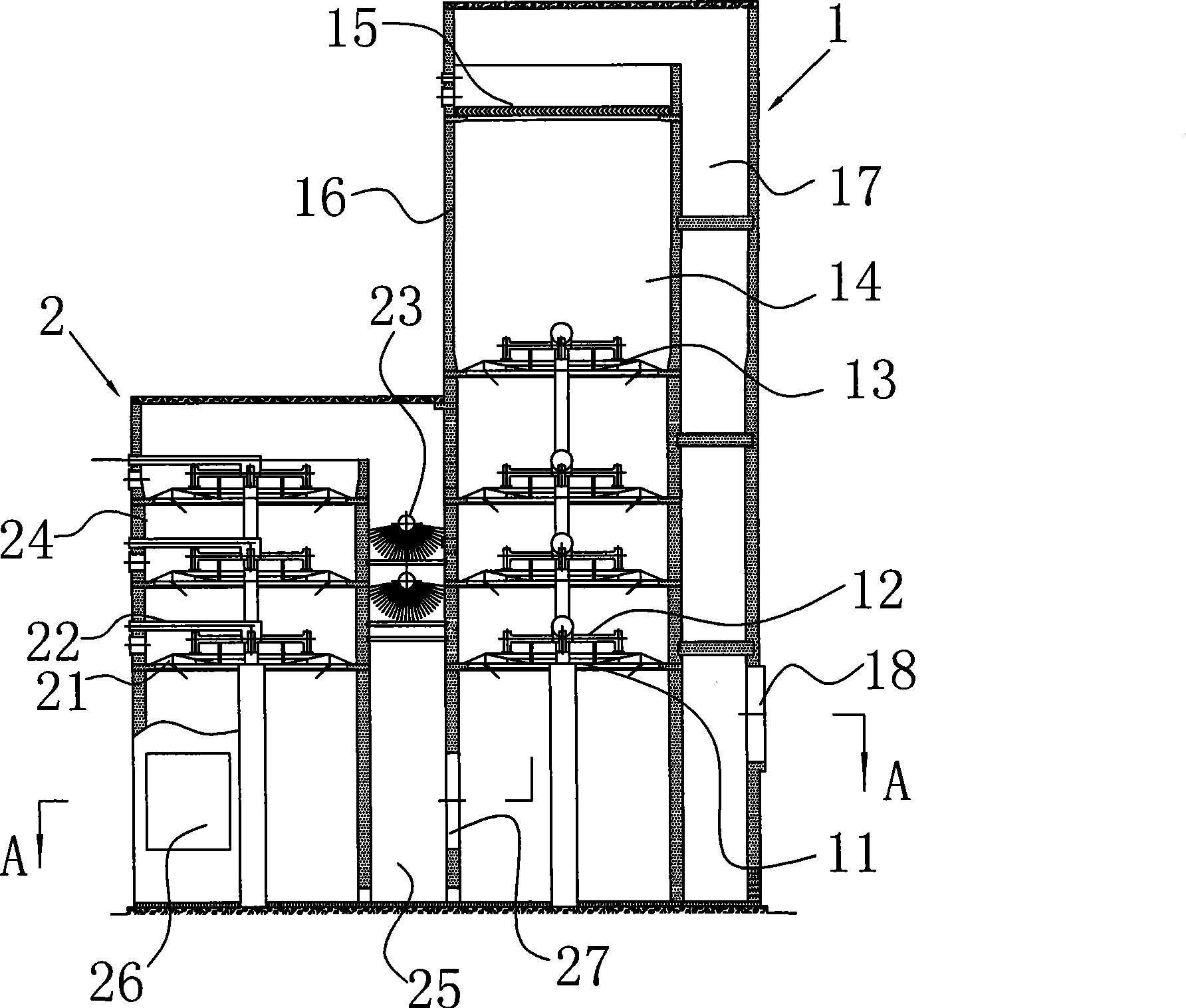
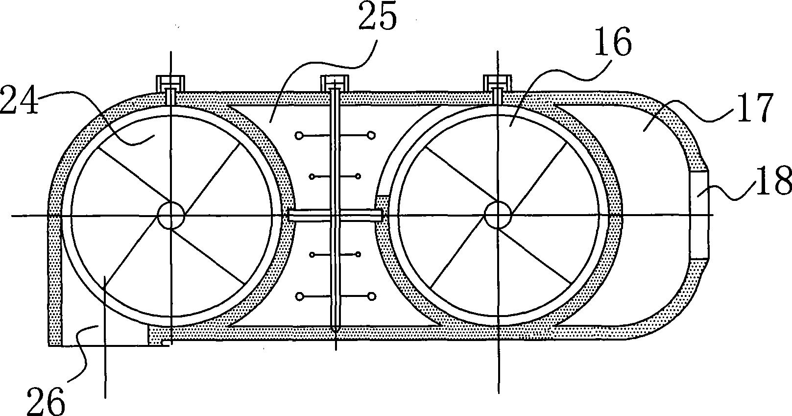
The invention discloses a duplex type desulfurizing and dedusting device which comprises at least one high tower that comprises a pneumatic diverting device, a spraying device, a flue gas dehydrating device and a dry section, and further comprises at least one low tower that only comprises a pneumatic diverting device and a spraying device; the low tower comprises a forestage tower and a sprayingtower, the pneumatic diverting device and the spraying device are arranged inside the forestage tower, a flue gas inlet is arranged on the forestage tower, the spraying tower has a spraying device inside, the forestage tower and the spraying tower are communicated at the tops thereof, and the spraying tower and the high tower are serially connected at the lower parts thereof. The duplex type desulfurizing and dedusting device has great desulfurizing and dedusting effects, can reach the desulfurizing efficiency up to 99 percent and the dedusting efficiency up to 99.6 percent which are detected, thus being much higher than the nation required indexes and having remarkable improvement on the desulfurizing and dedusting efficiency compared with the prior art.
Description
Duplex desulfurization and dust removal equipment technical field The invention relates to a flue gas desulfurization and dust removal equipment. Background technique Flue gas desulfurization and dust removal equipment is widely used in industrial furnaces such as power generation and smelting. Since the furnace produces a large amount of harmful gases and dust such as sulfur dioxide during the working process, it must be discharged into the atmosphere through desulfurization and dust removal to play an environmental protection role. . The current desulfurization and dust removal equipment is generally composed of one tower or more than one tower in parallel. The dust removal efficiency of this type of dust removal equipment is relatively low and the cost is relatively high. Although people have made many subtle improvements to improve its efficiency, the basic structure is still No change, each tower still has a pneumatic spray device, a flue gas dehydration device, and ...
Claims
Login to View More Application Information
Patent Timeline
 Patent Type & Authority Patents(China)
IPC IPC(8): B01D53/50B01D53/78B01D47/06
Inventor 杨培灿晏华邓杰
Owner HUNAN JIAYU ENVIRONMENT PROTECTION EQUIP
Features
- R&D
- Intellectual Property
- Life Sciences
- Materials
- Tech Scout
- Unparalleled Data Quality
- Higher Quality Content
- 60% Fewer Hallucinations
Learn More Browse by: Latest US Patents, China's latest patents, Technical Efficacy Thesaurus, Application Domain, Technology Topic, Popular Technical Reports.
© 2025 PatSnap. All rights reserved.Legal|Privacy policy|Modern Slavery Act Transparency Statement|Sitemap|About US| Contact US: help@patsnap.com


