
Vehicle automatic correction brake co-axial combined bottom fork

An automatic correction and brake technology, applied in axle suspension, bicycle accessories, transportation and packaging, etc., can solve the problems of energy and power waste, deterioration of vehicle operating conditions, and increase of vehicle maintenance costs, so as to save energy and power, prolong The effect of using cycle and prolonging service life

Inactive Publication Date: 2009-05-06
SOUTHWEST UNIV
View PDF0 Cites 4 Cited by
  • Summary
  • Abstract
  • Description
  • Claims
  • Application Information

AI Technical Summary

Problems solved by technology

If the coaxiality of the rear wheel shaft holes on the two leg tubes cannot be guaranteed during installation, the wheel bearings will be eccentrically rubbed, and the brake pads will also form a eccentrically rubbed friction pair, which will deteriorate the running condition of the vehicle, cause waste of energy and power, and increase vehicle repair costs
Especially for motor vehicles with adaptive automatic transmission, adaptive shifting requires relatively accurate torque transmission. If the axle installation is skewed, brake pads or other friction pairs will generate additional torque when the vehicle is running, it cannot guarantee accurate torque transmission. , affecting the normal action of the adaptive automatic transmission, it will also affect the normal operation of the vehicle

Method used


Image

  • Vehicle automatic correction brake co-axial combined bottom fork
  • Vehicle automatic correction brake co-axial combined bottom fork
  • Vehicle automatic correction brake co-axial combined bottom fork

Examples


Embodiment Construction

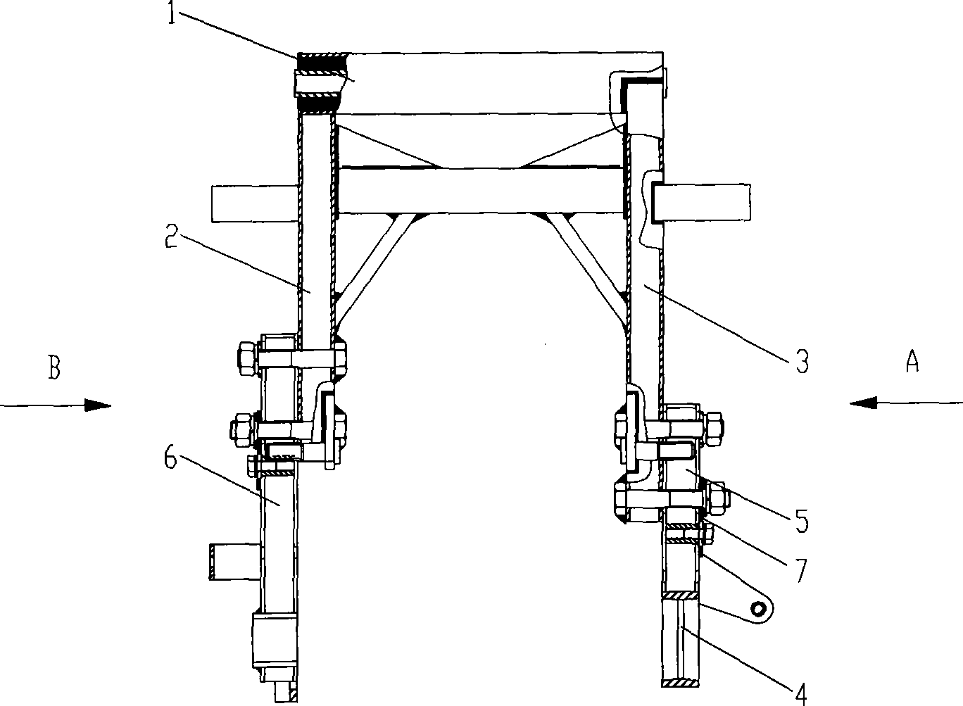
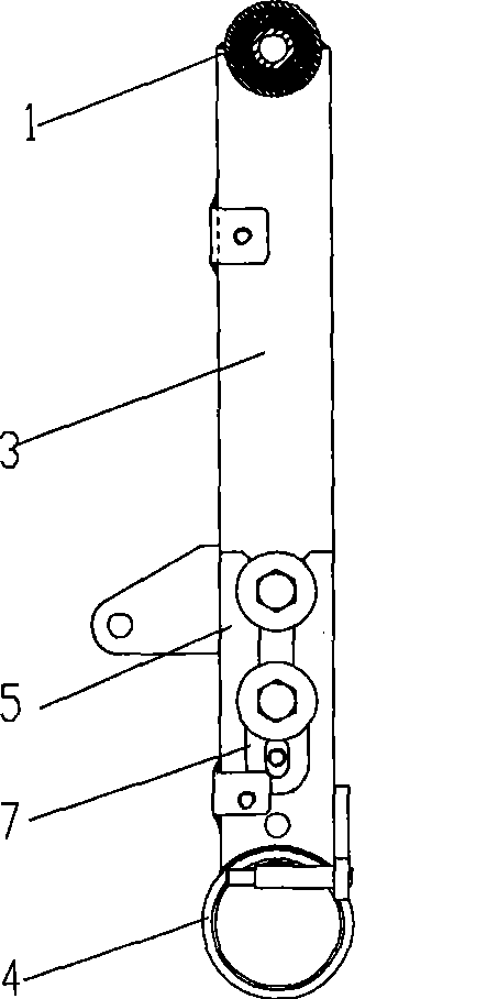
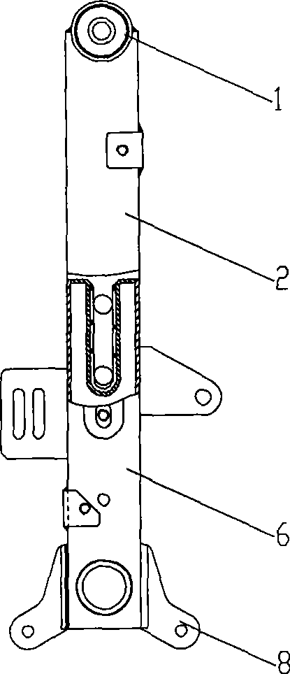
[0024] figure 1 It is a structural schematic diagram of the first embodiment of the present invention, figure 2 for figure 1 View along direction A, image 3 for figure 1 View along the B direction, as shown in the figure: the combined flat fork for automatically correcting the coaxiality of the brake of the motor vehicle in this embodiment includes the end shaft tube 1, the leg tube I 2 and the leg tube II 3, and the leg tube I 2 and the leg tube II 3 are respectively fixedly connected with the end shaft tube 1, the leg tube I2 is fixedly provided with the transmission mounting lug 8, and the leg tube II 3 is provided with the axle seat 4; during assembly, the brake 13 is fixedly arranged on the leg tube II 3, The axle seat 4 is set on the outer circle of the bearing seat 10 of the wheel shaft 9 to support the wheel axle 9. The diameter of the inner hole where the axle seat 4 cooperates with the bearing seat 10 gradually increases from the middle to both ends. In this emb...


PUM


Abstract

The invention discloses a combined bottom fork used for automatically correcting the brake coaxiality of motor vehicles, comprising an end axle tube, a leg tube I and a leg tube II, wherein, the leg tube I and the leg tube II are respectively and fixedly connected with the end axle tube, the leg tube I is fixedly provided with an installing suspension loop of a speed changer, and the leg tube II is provided with a wheel axle seat; and when assembling, a brake is fixedly arranged on the leg tube II, the wheel axle seat is sheathed on the excircle of a wheel axle bearing seat for supporting a wheel axle, and the diameter of an inner bore, by which the wheel axle seat is matched with the bearing seat, gradually increases from the center to two ends. The wheel axle seat can slightly swing relatively to the wheel axle, and automatically realize centering; when in use, each friction pair can be adjusted automatically, partial friction can not be caused, especially for the brake which is arranged fixedly and relatively to the leg tube, the partial friction of a friction plate to the wheel can be automatically eliminated, the energy and power are saved, and the service life of the friction pair components is prolonged; and in the installation process, the coaxiality of each friction pair can be conveniently ensured, the friction is avoided, and the service cycle of all the friction pair components is prolonged.

Description

technical field [0001] The invention relates to a flat fork for a motor vehicle, in particular to a combined flat fork for automatically correcting the coaxiality of a brake of a motor vehicle. Background technique [0002] The flat fork is an important part of the motor vehicle and belongs to the suspension device. The flat fork includes two-leg tubes, and the end shaft tubes that are fixedly connected to the two-leg tubes; the two-leg tubes of the prior art are provided with rear wheel axle holes for installing rear wheels; the flat fork and the rear wheels support the vehicle frame on the road surface together In general, the rigidity of the fork and wheel of the motor vehicle is relatively large, and it is treated as rigid in theory. Therefore, the coaxiality of the rear wheel axle holes on the two leg tubes plays an important role in the normal driving of the vehicle. If the coaxiality of the rear wheel shaft holes on the two leg tubes cannot be guaranteed during insta...

Claims


Application Information

Patent Timeline
Patent Type & Authority Applications(China)
IPC IPC(8): B62K25/04
Inventor 薛荣生林毓培郝允志
Owner SOUTHWEST UNIV
Learn More