
Band steel electrolytic degreasing bath

An electrolytic degreasing, strip steel technology, applied in the electrolytic process, electrolytic components, coatings, etc., can solve the problems of galvanizing troublesome, difficult to wash off, etc., and achieve the effect of ensuring the cleaning effect

Inactive Publication Date: 2009-05-06
CHANGSHU HUAYE STEEL STRIP
View PDF0 Cites 6 Cited by
  • Summary
  • Abstract
  • Description
  • Claims
  • Application Information

AI Technical Summary

Problems solved by technology

Especially, when the unit is in the end-to-end welding of the strip steel, the cleaning section unit shuts down, and the impurity on the surface of the lye in the electrolytic degreasing tank tends to adhere stubbornly to the surface of the strip steel in the electrolytic tank and It is brought into the next water scrubbing process in the cleaning section, and it is difficult to wash it off in the next water scrubbing process, causing trouble for galvanizing

Method used


Image

  • Band steel electrolytic degreasing bath
  • Band steel electrolytic degreasing bath

Examples


Embodiment 1

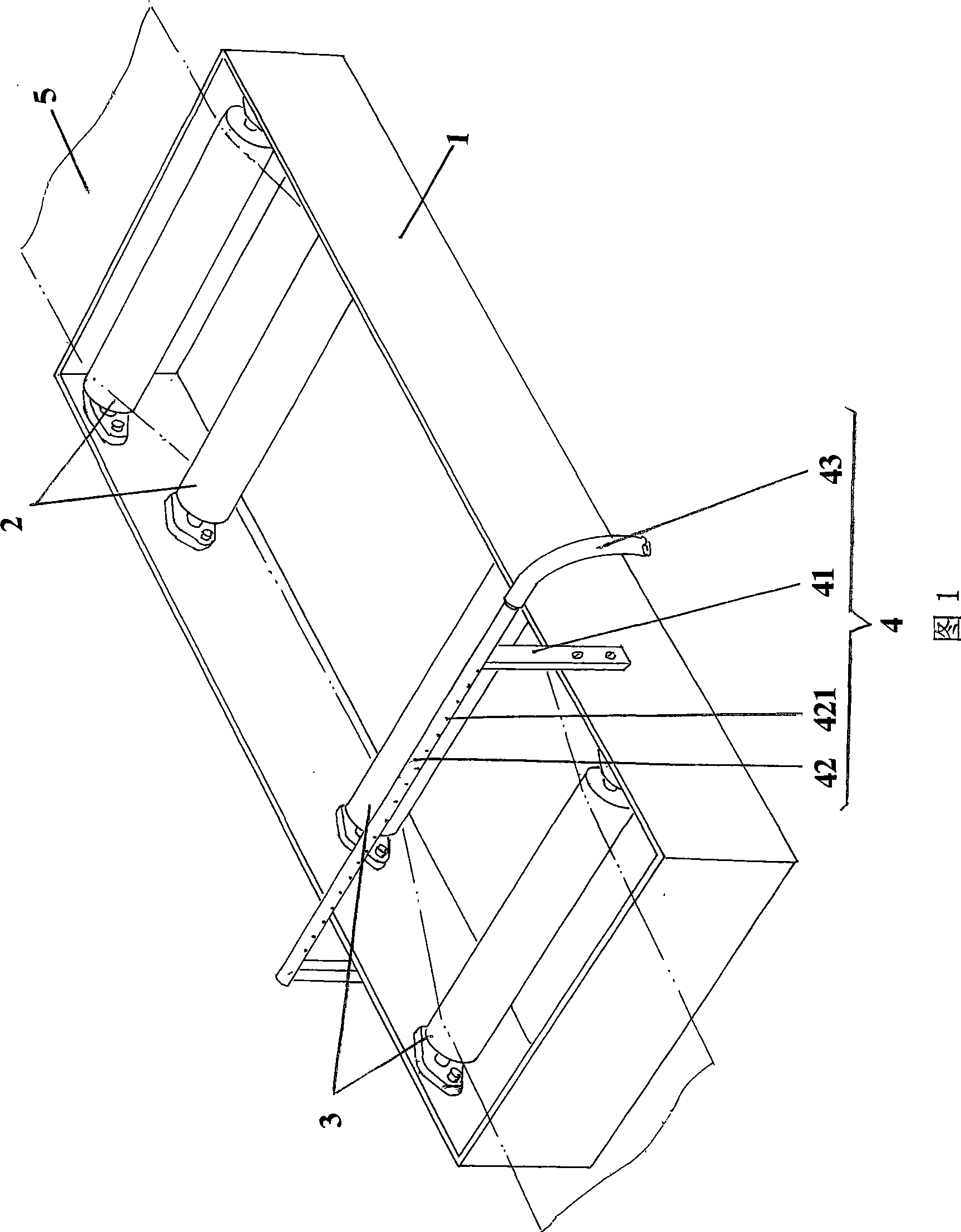
[0016] See also Fig. 1, have provided the known public strip steel degreasing electrolyzer of the industry in the prior art, the tank body 1 of this strip steel electrolytic degreasing tank is the shape of a cuboid, is configured in the chamber of the tank body 1 for removing strip Electrolytic degreasing solution such as lye for the grease on the surface of steel 5. One end of the tank body 1, that is, the right end of the current position shown in Figure 1, is provided with a pair of strip steel introduction rollers 2, specifically: the two ends of the strip steel introduction roller 2 and the corresponding inner wall of the tank body 1 use bearings and add bearings The seat and the tank body 1 are pivoted, and the concept of pivoting mentioned here is a rotatable setting. In this embodiment, although a pair of strip steel lead-in rollers 2 is shown, it can be reasonably increased as required, for example, three or four (ie, two pairs) of strip steel lead-in rollers 2 . A p...

Embodiment 2

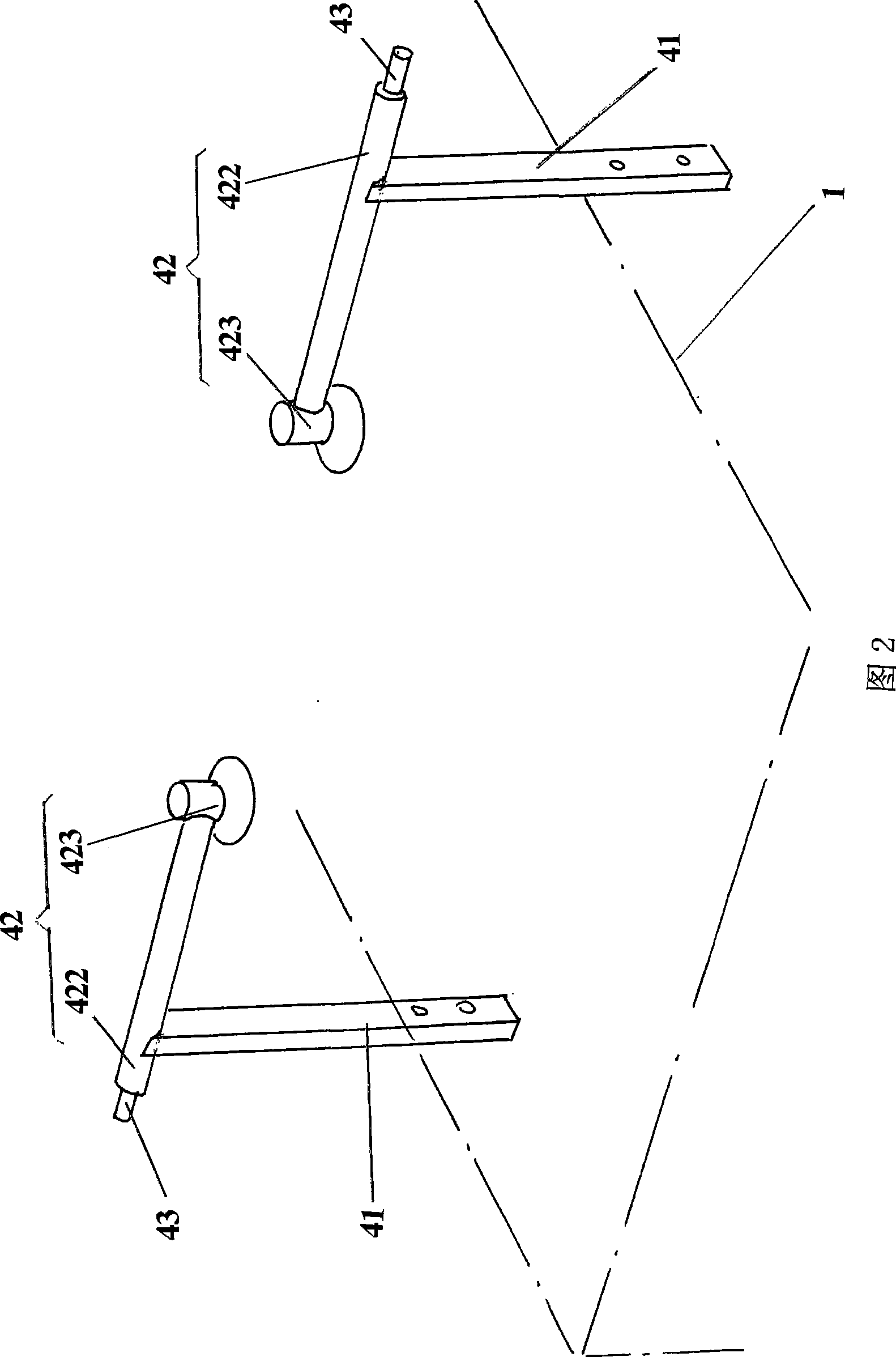
[0020] Please see Fig. 2, another embodiment of shower device 4 is provided, in this embodiment, shower device 4 comprises a pair of brackets 41, a pair of showers 42 and a pair of water pipes 43, a pair of brackets The lower end of 41 is fixed to the corresponding two outer walls of the tank body 1, and a shower 42 is respectively fixed on the upper ends of a pair of brackets 41. Each shower 42 includes a cantilever tube 422 and a spray head 423, and one end of the cantilever tube 422 Fixed with the upper end of the bracket 41, the other end of the cantilever pipe 422 is fixed with the spray head 423, and a pair of water pipes 43 are respectively connected with the corresponding cantilever pipe 422. On the lower strip 5. All the other are the same as the description of embodiment 1.


PUM


Abstract

The invention relates to a strip steel degreasing electrolytic cell, which belongs to the technical field of a production facility of hot-galvanized strip steels. The strip steel degreasing electrolytic cell comprises a cell body, a pair of strip steel guide-in rollers which are arranged on one end of the cell body, and a pair of strip steel guide-out rollers which are arranged on the other end of the cell body, and is characterized in that the strip steel degreasing electrolytic cell also comprises a spray system, wherein the spray system is fixed on the cell body and corresponds to the upper part between the pair of strip steel guide-out rollers. The strip steel degreasing electrolytic cell has the advantages that the strip steel degreasing electrolytic cell can implement spraying on strip steels which are discharged from the cell body of the degreasing electrolytic cell, remove oil stain impurities which are adhered to the surfaces of the strip steels and come from the lye surface in the cell body of the degreasing electrolytic cell, and prevent the oil stain impurities from being carried to the next procedure, so that the strip steel degreasing electrolytic cell can guarantee the surface cleaning effect of the strip steels and provide guarantee the water scrubbing effect of the next water scrubbing procedure, and can not generate the plating leakage phenomenon in the hot galvanizing procedure.

Description

technical field [0001] The invention belongs to the technical field of production facilities for hot-dip galvanized strip steel, and in particular relates to an electrolytic degreasing tank for strip steel. Background technique [0002] It is well known in the industry that before the strip is put into hot-dip galvanizing, the surface of the strip needs to be cleaned, and the strip electrolytic degreasing tank is to remove the oil stain left on the surface of the strip during rolling. The mechanism of electrolytic degreasing is that the electrolytic cell is electrolyzed by electrodes, and the water in the alkali solution in the tank precipitates hydrogen and oxygen bubbles on the surface of the strip steel, destroying the oil film attached to the surface of the strip steel, and the bubbles are detached from the strip steel attached to the oil droplets. Residing on the surface of the oil droplet and staying on the interface between the oil and the degreasing liquid, due to th...

Claims


Application Information

Patent Timeline
IPC IPC(8): C25F1/00C25F7/00C23C2/02
Inventor 秦燕君周建平张洵陆云元曾小逞王珏
Owner CHANGSHU HUAYE STEEL STRIP
Learn More