Pulsating heat pipe with stable one-way circulation flow

A pulsating heat pipe and one-way circulation technology, applied to indirect heat exchangers, lighting and heating equipment, etc., can solve the problems of difficulty in maintaining one-way circulation flow and complicated operation phenomena, and achieve improved working fluid transportation and heat transfer performance , enhance the effect of stability and controllability

Inactive Publication Date: 2009-05-06
NORTH CHINA ELECTRIC POWER UNIV (BAODING)
View PDF0 Cites 13 Cited by
  • Summary
  • Abstract
  • Description
  • Claims
  • Application Information

AI Technical Summary

Problems solved by technology

However, in actual operation, it is difficult to maintain a stable one-way circulation flow, which usually intersects with flow states such as local pulsation, stagnation, and reverse f

Method used


Image

  • Pulsating heat pipe with stable one-way circulation flow
  • Pulsating heat pipe with stable one-way circulation flow
  • Pulsating heat pipe with stable one-way circulation flow

Examples


Embodiment 1

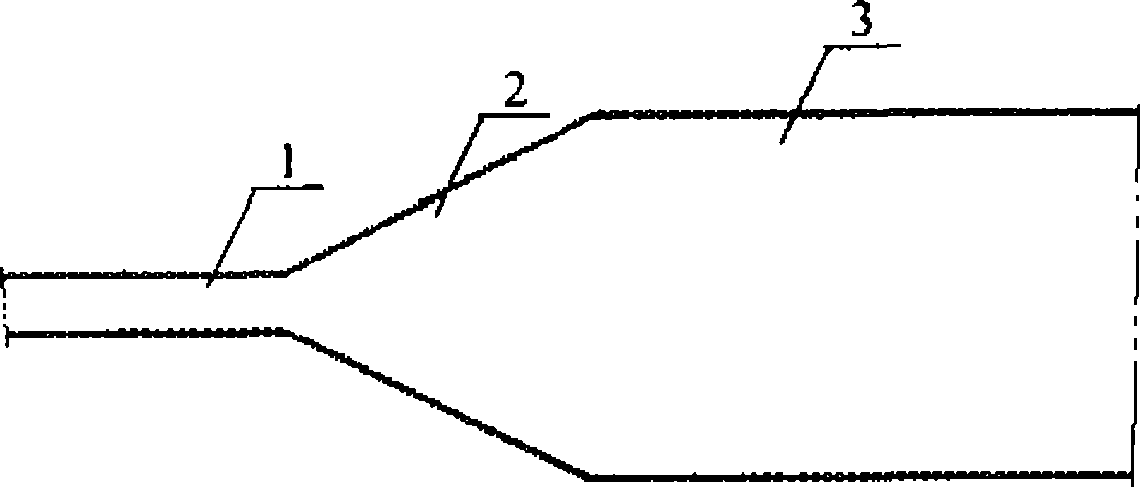
[0019] Such as figure 1 As shown, the pulsating heat pipe is formed by connecting a section of expander tube between two sections of tubes with different inner diameters. That is, a section of expanding pipeline 2 is connected between the thin tube 1 and the thick tube 3 to form a complete flow channel.

Embodiment 2

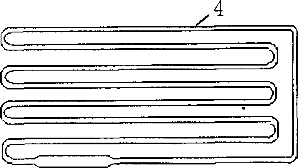
[0021] Such as figure 2 Shown is a modified pulsating heat pipe. The pipe is bent into multiple elbows, the liquid in the pipe is heated and cooled, and a phase change occurs, and heat is transferred through the phase change process and the flow of the working fluid, and the pulsating heat pipe can cool the electronic device. A section of thick pipe with a length of 100mm and an inner diameter of 2mm is installed on the lower left part of the pipeline; the inner diameter of the other parts remains 1.6mm. This structural improvement is equivalent to applying the new structure of the present invention to the rightmost pipeline.

[0022] A piece of thick pipe installed destroys the symmetry and balance of the flow path of the pulsating heat pipe, and its effect is similar to a one-way valve, which makes the flow of the working medium in the pulsating heat pipe dominant in one direction, thus improving the possibility of forming a one-way circulating flow possibility.

[0023]...

Embodiment 3

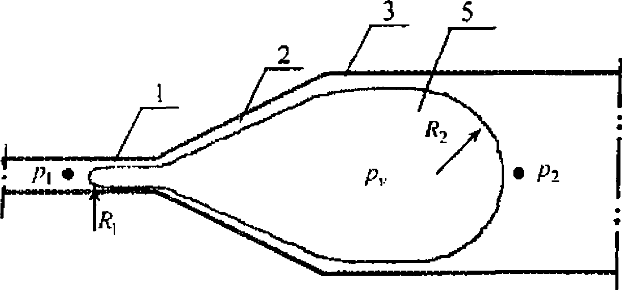
[0025] image 3 is a schematic diagram of the micropump effect. In the expanding pipeline 2, if bubbles 5 are generated periodically, since the shape of the pipeline is gradually expanding, the radius of curvature of the meniscus of the bubbles will change forcibly, and a micropump effect will be produced under the action of surface tension.

[0026] The effect of surface tension creates a pressure difference between the inside of the bubble and the outside liquid,

[0027] p v - p 1 = 2 σ R 1 p v - p 2 = 2 σ R 2

[0028] Therefore there is, p 1 - ...


PUM


Abstract

The invention discloses a pulsating heat pipe with steady and monodirectional circular flow, which belongs to the range of heat transfer elements. The pulsating heat pipe is formed by connecting a section of increasing coupling between two pipes with different inside diameters, wherein the increasing coupling can reduce symmetry and harmony of a flow passage, match the flowed friction reasonably, and generate the micropump effect due to the action of the liquid-vapor surface tension to guide work substances to move towards the thick pipe, so as to form monodirectional circular flow. The pulsating heat pipe has the advantages that the pulsating heat pipe has a simple structure, good reliability, and multiple realizing patterns; and the new structure adopted can strengthen stability and controllability of operation of the pulsating heat pipe, and improve heat transfer property of the pulsating heat pipe.

Description

technical field [0001] The invention belongs to the range of heat transfer elements, and in particular relates to a pulsating heat pipe with stable unidirectional circulating flow which can make the two-phase flow in the pulsating heat pipe have directionality and help realize unidirectional circulating flow. Background technique [0002] The pulsating heat pipe is a high-efficiency heat transfer element. The pulsating heat pipe uses phase change to generate bubbles to drive the flow of working fluid. Although the structure is relatively simple, its internal mechanism is very complicated, involving multidisciplinary and multiparameter vapor-liquid two-phase flow systems. And theoretical research is still in its infancy. [0003] The flow inside the pulsating heat pipe belongs to the gas-liquid two-phase flow in the micro channel. During the operation, the pressure, temperature and speed of the working fluid inside it are pulsating, and there are many thermal imbalance phenom...

Claims


Application Information

Patent Timeline
IPC IPC(8): F28D15/02
CPCF28D15/0266
Inventor 刘石李惊涛李志宏韩振兴
Owner NORTH CHINA ELECTRIC POWER UNIV (BAODING)
Why Eureka
Try Eureka