
Inductive eddy current actuating element and method for producing an inductive dampening element

A technology of actuating elements and damping elements, applied in the direction of electrical components, electrical devices, printed circuit manufacturing, etc., can solve the problems that the bell curve is wide, not enough to form a bell curve, and cannot determine the vertex accurately enough to achieve Achieve precise imprinting, easy geometric shape, and small error effects

Inactive Publication Date: 2011-01-12
ZF FIEDRICHSHAFEN AG
View PDF4 Cites 0 Cited by
  • Summary
  • Abstract
  • Description
  • Claims
  • Application Information

AI Technical Summary

Problems solved by technology

If a relatively short rhombus is selected, only two signal values ​​will appear at some measurement points (stop points), which is not enough to form a bell curve; if a longer rhombus is selected, the bell curve will become Unnecessarily wide and will not be able to determine vertices accurately enough (too little position selectivity)

Method used


Image

  • Inductive eddy current actuating element and method for producing an inductive dampening element
  • Inductive eddy current actuating element and method for producing an inductive dampening element
  • Inductive eddy current actuating element and method for producing an inductive dampening element

Examples


Embodiment Construction

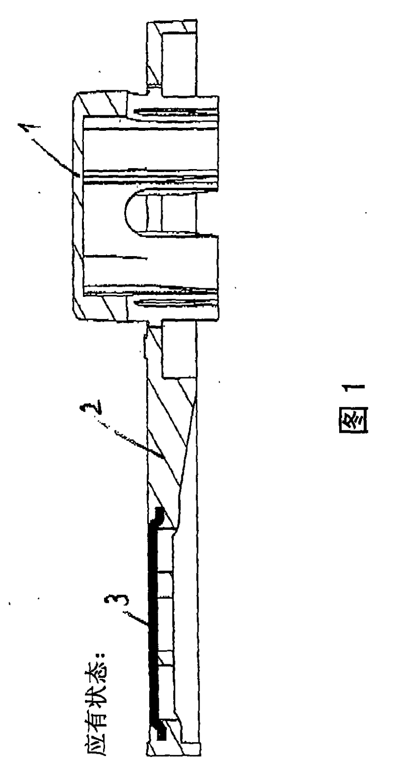
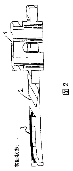
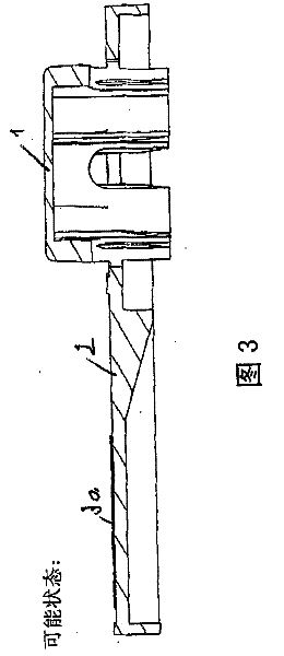
[0038] attached figure 1 and 2 Shown is a cross-section of a rotor 1 comprising a damping element 3 produced according to the prior art. The damping element 3 consists of a copper sheet which is encapsulated in the pivot arm 2 by injection molding, ie it is encapsulated by injection molding. attached figure 1 The state shown in is the expected state, and the rotors 1, 2, and 3 are not distorted due to temperature changes; figure 2 Shown in actual state, the rotors 1, 2, 3 have been distorted by temperature changes, especially by the cooling process after injection moulding.

[0039] attached figure 1 Shown as expected state with attached figure 2 The difference between the actual states shown is due to differences in the coefficients of thermal expansion. The copper or aluminum sheet 3 has a different longitudinal coefficient of thermal expansion than the plastic arm 2 . This distortion can lead to failure to observe machining tolerances, or cause fluctuations in s...


PUM


Abstract

The present invention relates to a method for manufacturing an inductive damping element, such as a damping element of inductive transducer, wherein the transducer can generate a coil signal changing along with moving distance or angle under the function of eddy-current damping. A conductive metal film replaces the metal piece punched by copper, aluminium or brass. In the process for manufacturing rotor or sliding block loaded with inductive damping element, metal film is released from the material coil and is impressed on a plastic carrier, and simultaneously the metal film is punched with ahot die. Then the residual part of metal film is coiled on a second material coil. The invention also introduces an inductive eddy-current actuating component which can be caused to pass through a row of pancake coils or flat coils which are adjacent closely so that the inductance of three coils can be changed through the eddy-current damping effect. The profile shape of inductive actuating component basically has a diamond shape and is characterized in that at least two edges of diamond bend inwards.

Description

technical field [0001] The invention relates to an inductive eddy current actuating element. A device of this type is disclosed, for example, in patent document EP 1 672 323 A2. Background technique [0002] Such actuating elements are displaced at a predetermined distance over a row of closely spaced flat coils, also called flat coils. This involves a relative movement, ie in principle it is possible to move either the inductive actuating element, or a row of flat coils, or both. Measurements are based on relative motion only. [0003] The device can be used as a measuring device for changing the inductance of essentially three coils in a coil row by means of eddy current damping. For example, the appendix to the specification of the patent application Figure 5 Shown is a flat coil row arranged in a straight line, and accompanying drawing 15 shows a coil row arranged in an arc. The position of the slide or rotor relative to the coil row can be determined, i.e. the trav...

Claims


Application Information

Patent Timeline
Patent Type & Authority Patents(China)
IPC IPC(8): G01B7/02G01B7/30H05K3/10H05K3/20
CPCG01D5/202G01D5/2013G01D5/2006
Inventor 托马斯·鲁博汉斯-路德维西·格茨凯克·威尔纳贝克·威尔纳
Owner ZF FIEDRICHSHAFEN AG
Learn More