Integrated fuel cell humidifying system
A fuel cell, integrated technology, used in fuel cells, fuel cell additives, solid electrolyte fuel cells, etc., can solve the problems of pipelines occupying a large space, occupying a large space, and installation space is limited, etc., to improve the weight-to-weight ratio power and volume specific power, small volume and weight, and the effect of taking up less space
- Summary
- Abstract
- Description
- Claims
- Application Information
AI Technical Summary
Problems solved by technology
Method used
Image
Examples
Embodiment 1
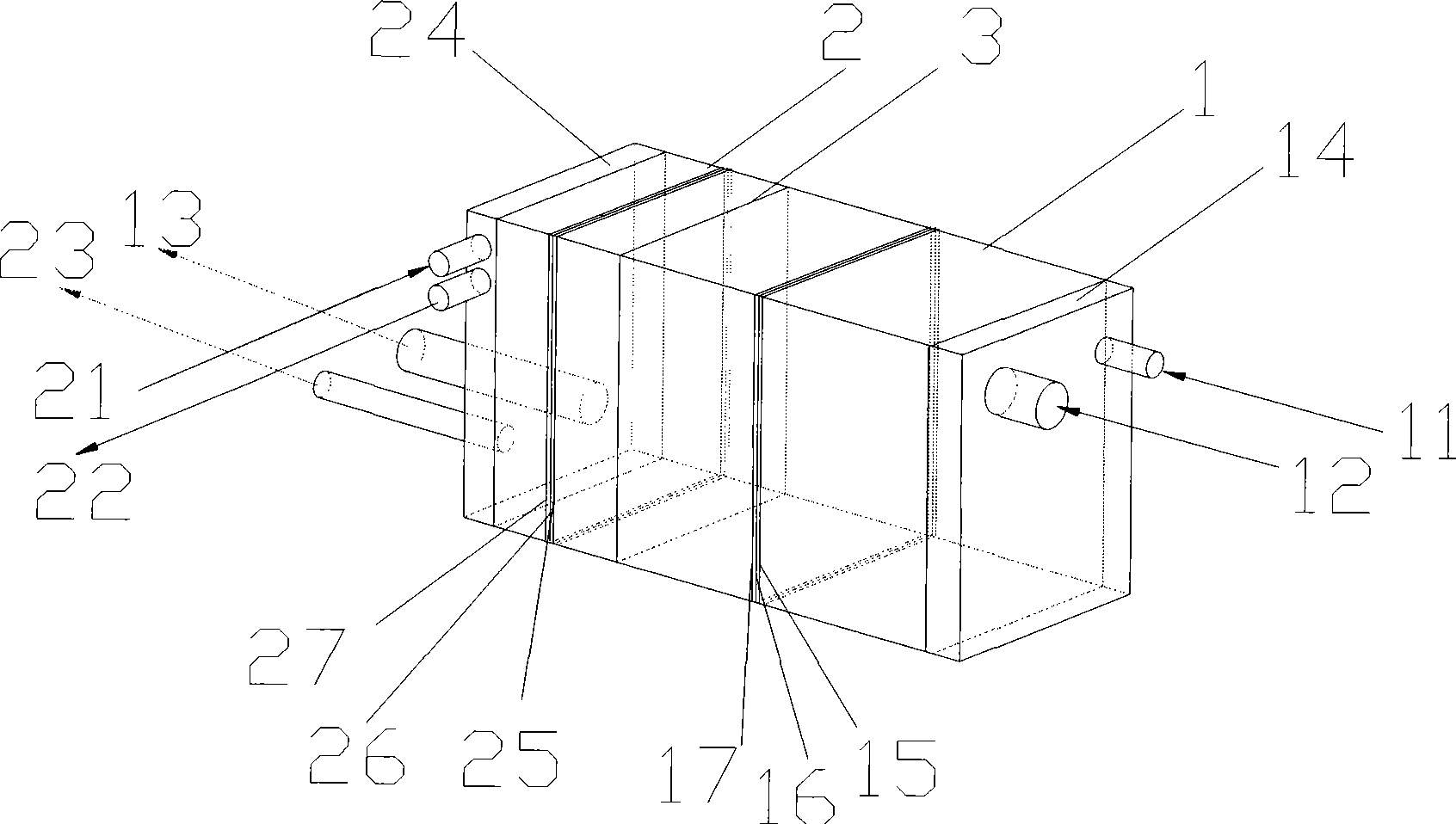
[0035] like figure 1 As shown, the humidification system of a 50kw car engine has a length of 550mm, a width of 210mm, and a height of 240mm. 3. The air humidification stack 1 and the hydrogen humidification stack 2 are respectively arranged on both sides of the partition plate 3 to form an air-hydrogen integrated humidification device. Air enters from the air inlet pipe 12 on the side of the air humidification stack 1 to humidify After that, it flows out from the air outlet pipeline 13 on the hydrogen humidification stack 2 side, and the cooling water enters from the cooling water pipeline 11 on the air humidification stack side, flows out from the cooling water pipeline 23 on the hydrogen humidification stack 2 side, and the hydrogen flows from the hydrogen humidification stack The hydrogen inlet pipe 21 on the 2 side enters, and after humidification, it flows out from the hydrogen outlet pipe 22 on the 2 side of the hydrogen humidification stack.
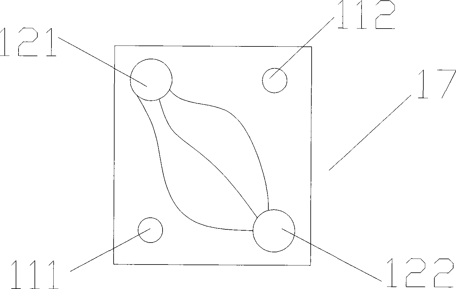
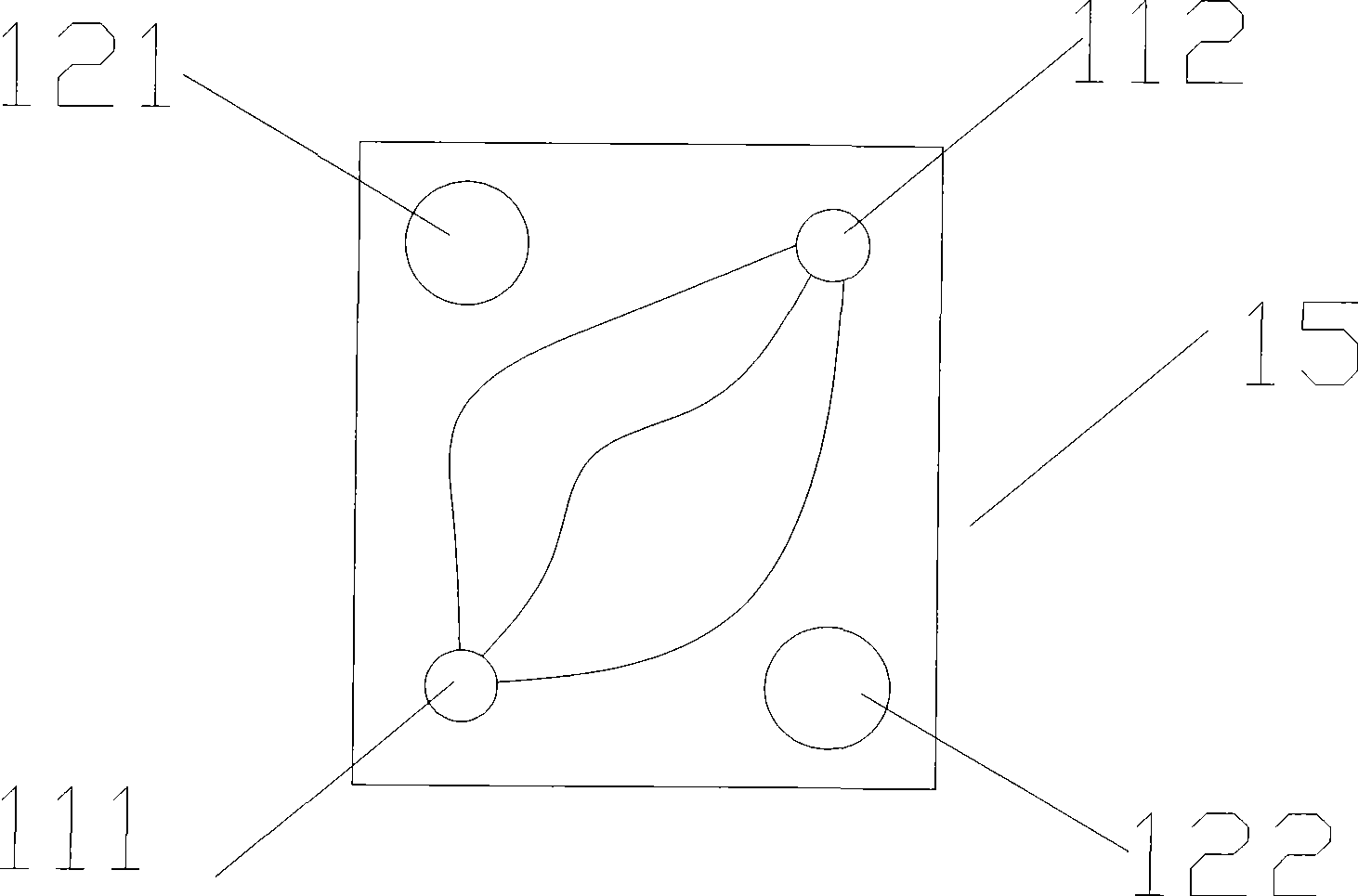
[0036] like Figure 1~3...
Embodiment 2
[0042] see Figure 1 to Figure 6 , 100kw city bus fuel cell engine humidification system, length 600mm, width 400mm, height 300mm, the system includes air humidification stack, hydrogen humidification stack, air side end plate, hydrogen side end plate, partition, the partition There are cooling water diversion grooves on both sides of the plate, and cooling water inlet and outlet holes and hydrogen outlet holes are arranged on the upper and lower ends of the partition. The hydrogen outlet channel of the wet stack flows out; or the hydrogen flows in from the air-side end plate, passes through the hydrogen outlet channel and partition of the air humidification stack, enters the hydrogen humidification stack for humidification, and then flows out from the hydrogen side end plate.
[0043] The air enters the air humidification stack from the air side end plate and after being humidified, returns and flows out from the air side end plate, and the cooling water enters the humidifica...
Embodiment 3
[0045] see Figure 1 to Figure 6 , a humidification system for a forklift fuel cell engine, with a length of 300mm, a width of 250mm, and a height of 250mm. The system includes an air humidification stack, a hydrogen humidification stack, an air side end plate, a hydrogen side end plate, and a separator. Cooling water diversion grooves are provided on both sides of the partition, and cooling water inlet and outlet holes are provided at the left and right ends of the partition. Hydrogen enters the hydrogen humidifying stack from the hydrogen side end plate after humidification, and returns to flow out from the hydrogen side end plate. The air enters the air humidifying stack from the air-side end plate to be humidified, and returns to flow out from the air-side end plate. The cooling water enters the humidification system from the hydrogen side end plate and flows out from the air side end plate. The air humidification stack is composed of 10 sets of cooling water deflectors, 2...
PUM
 Abstract
Description
Claims
Application Information
 - R&D
- Intellectual Property
- Life Sciences
- Materials
- Tech Scout
- Unparalleled Data Quality
- Higher Quality Content
- 60% Fewer Hallucinations
Browse by: Latest US Patents, China's latest patents, Technical Efficacy Thesaurus, Application Domain, Technology Topic, Popular Technical Reports.
© 2025 PatSnap. All rights reserved.Legal|Privacy policy|Modern Slavery Act Transparency Statement|Sitemap|About US| Contact US: help@patsnap.com


