

Bipolar secondary battery, battery asembly formed by connecting said batteries and vehicle mounting same
A secondary battery and bipolar technology, applied in the direction of secondary batteries, secondary battery manufacturing, battery components, etc., can solve the problem of reducing the performance of bipolar secondary batteries and increasing the internal resistance of bipolar secondary batteries , power reduction and other issues, to achieve the effect of suppressing weight, preventing resistance increase, and high power density
- Summary
- Abstract
- Description
- Claims
- Application Information
AI Technical Summary
Problems solved by technology
Method used
Image

Examples
no. 1 Embodiment approach
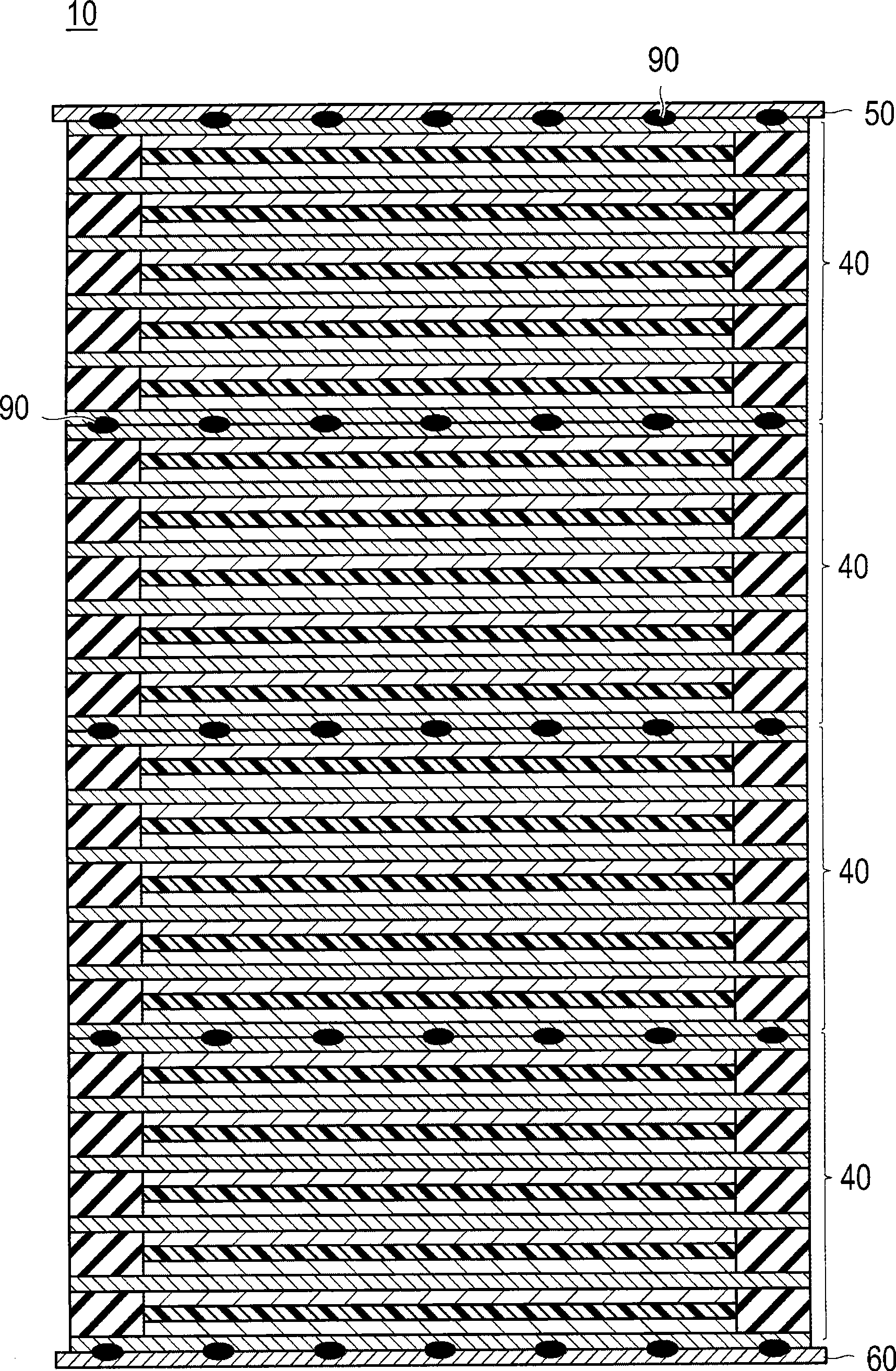
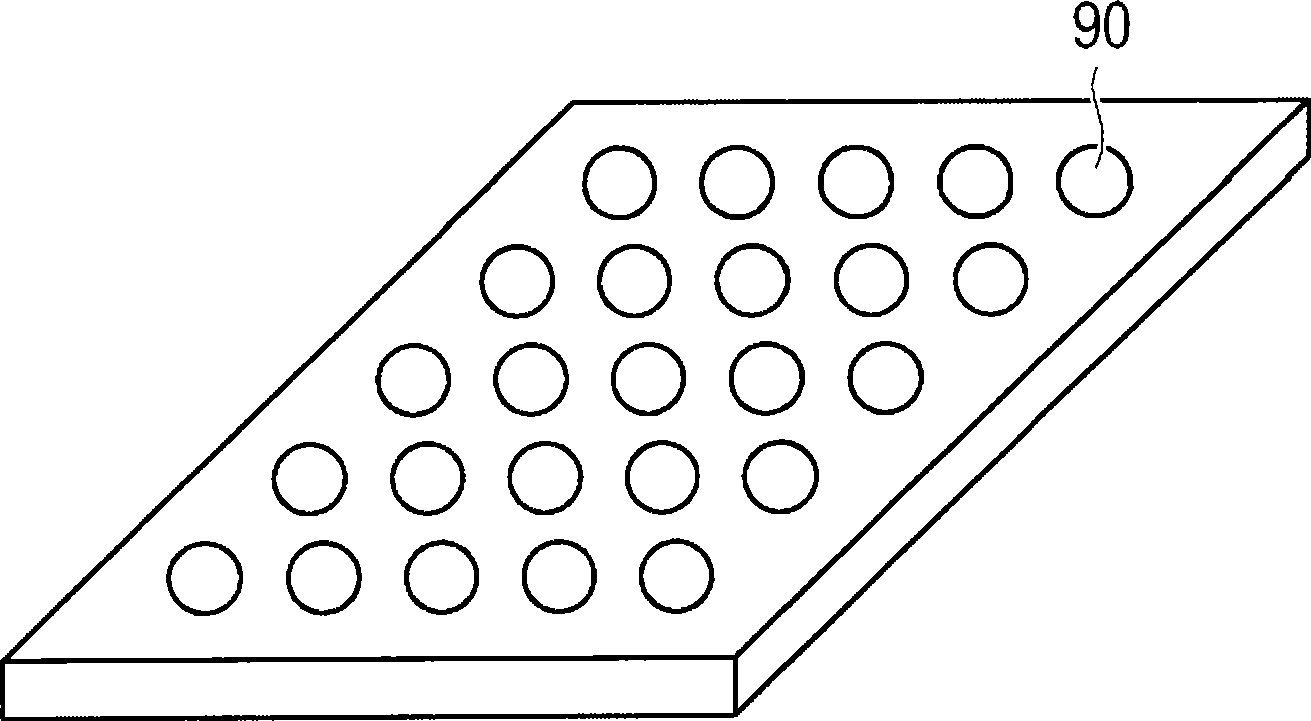
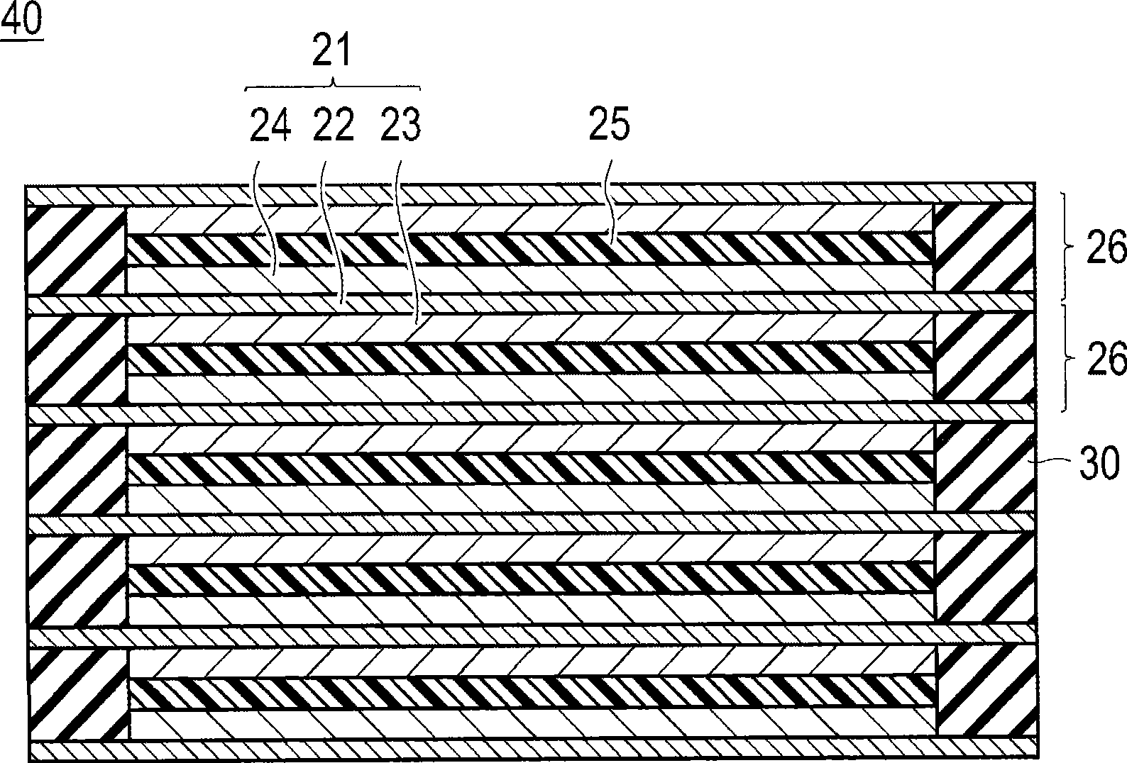
[0038] Figure 1A is a cross-sectional view of a bipolar secondary battery according to a first embodiment of the present invention, Figure 1B yes means Figure 1A The figure of the bonding part of the bipolar secondary battery shown. figure 2 It is a cross-sectional view of a bipolar battery stack constituting the bipolar secondary battery shown in FIG. 1 . image 3 is constituted figure 2 The cross-sectional view of the bipolar electrode of the bipolar battery laminate shown. Figure 4 is for illustration figure 2 The figure of the single cell layer which the bipolar battery laminated body shown has. Figure 5 is expressed in image 3 The figure which shows the state which arrange|positioned the sealing precursor in the outer peripheral part of the bipolar electrode. Figure 6 It is a diagram showing a state where a separator is provided on a bipolar electrode on which a sealing precursor is arranged, and a sealing precursor (the same portion as the portion where th...
no. 2 Embodiment approach
[0101] The basic structure of the bipolar battery 10 of the second embodiment and the Figure 6 The first embodiment described is the same, and therefore description of its structure is omitted. The only difference between the first embodiment and the second embodiment lies in the bonding of the bipolar battery stacks 40 to each other and between the bipolar battery stacks 40 and the electrode tabs 50 and 60 . Bonding pattern.
[0102] Fig. 8 shows the bonding pattern of the second embodiment. This bonding pattern is formed not on the cell reaction portion of the bipolar battery stack 40 but on the sealing portion. Variations 1 to 3 are shown as specific installation patterns.
[0103] Variation 1 of FIG. 8 provides the four corners of the sealing part with a predetermined size of the adhesive part.
[0104] Variation 2 in FIG. 8 provides the adhesive portions at a plurality of positions on the sealing portion with predetermined sizes and at predetermined intervals. Here,...
no. 3 Embodiment approach
[0108] The basic structure of the bipolar battery 10 of the third embodiment and the Figure 6 The first embodiment described is the same, and therefore description of its structure is omitted. The only difference between the first embodiment and the third embodiment lies in the bonding of the bipolar battery stacks 40 to each other and between the bipolar battery stacks 40 and the electrode tabs 50 and 60 . Bonding pattern.
[0109] Fig. 9 shows the bonding pattern of the third embodiment. The bonding pattern is provided such that the position of the center of gravity of the bonding portion 90 formed on the bonding surface of the bipolar battery stack 40 on the bonding surface coincides with the position of the center of gravity of the bipolar battery stack 40 . Variations 1 to 3 are shown as specific installation patterns.
[0110] Variation 1 in FIG. 9 forms the bonding portion in a quadrangle of a predetermined size, and is an installation pattern in which the position ...
PUM
| Property | Measurement | Unit |
|---|---|---|
| thickness | aaaaa | aaaaa |
| thickness | aaaaa | aaaaa |
| thickness | aaaaa | aaaaa |
Abstract
Description
Claims
Application Information