
Method for IP backbone network flow load balance based on BGP virtual next hop

A traffic and balance technology, applied in the direction of network interconnection, data exchange network, data exchange through path configuration, etc., can solve the problem of traffic forwarding bias and so on

Active Publication Date: 2009-05-06
CHINA MOBILE GRP GUANGDONG CO LTD
View PDF0 Cites 13 Cited by
  • Summary
  • Abstract
  • Description
  • Claims
  • Application Information

AI Technical Summary

Problems solved by technology

The core router only has the route sent by the "Router-ID small router", so it will only select the route to the "Router-ID small router", as in Figure 4 As shown, 100% of the traffic is loaded on one side of the link, while the other side of the link has no traffic, which causes the bias of traffic forwarding

Method used


Image

  • Method for IP backbone network flow load balance based on BGP virtual next hop
  • Method for IP backbone network flow load balance based on BGP virtual next hop
  • Method for IP backbone network flow load balance based on BGP virtual next hop

Examples


Embodiment Construction

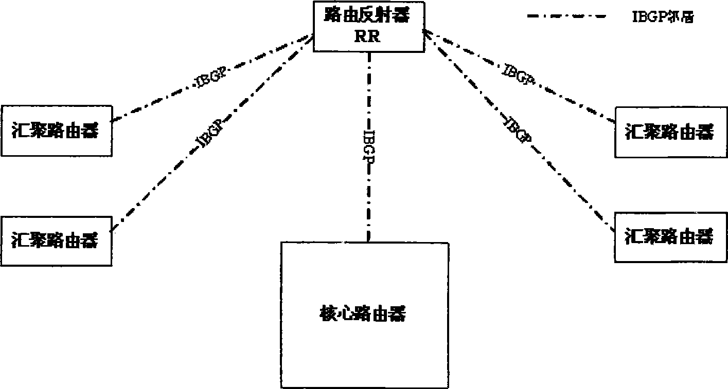
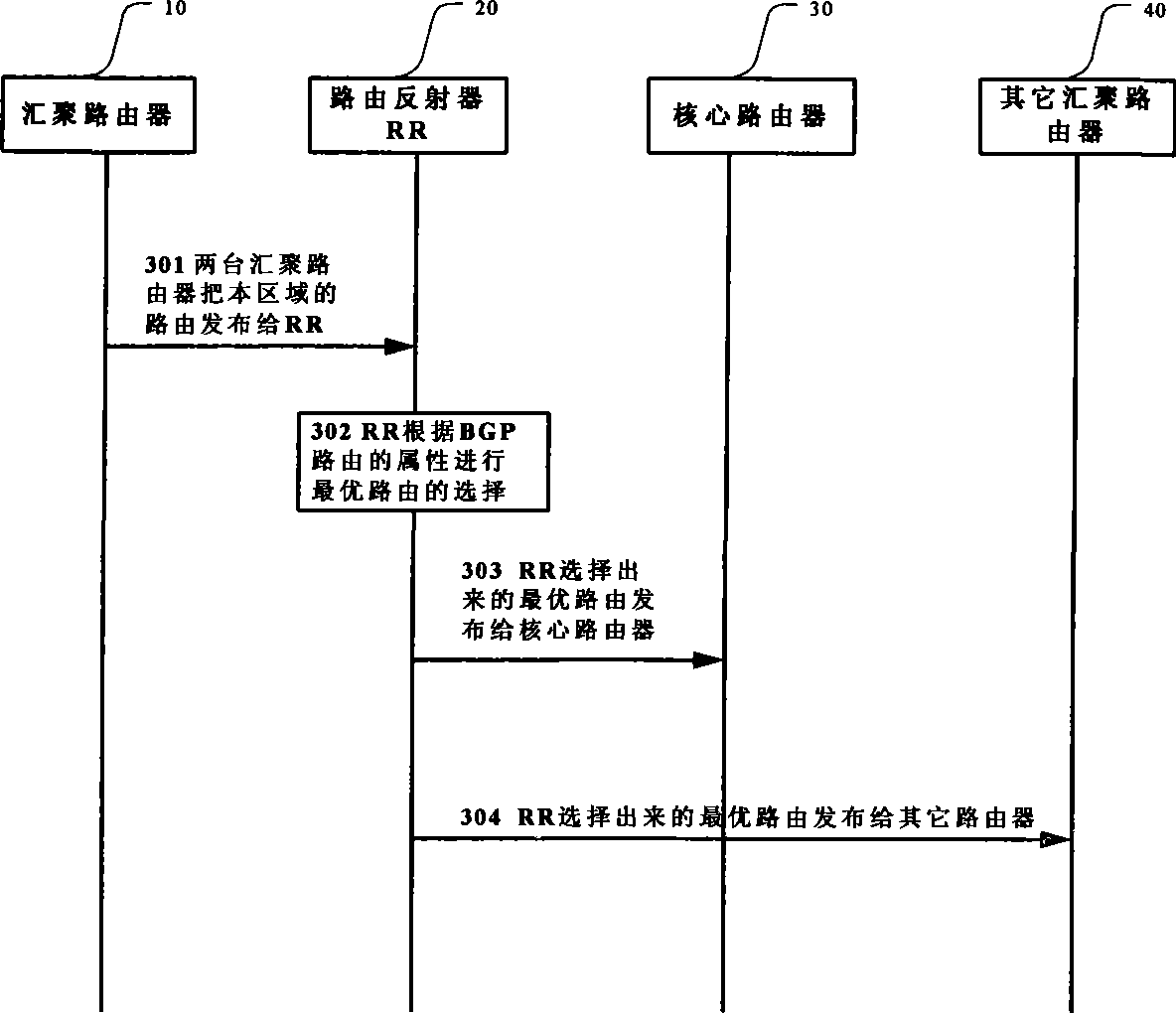
[0023]According to the present invention, by changing the Nexthop attribute in the source BGP routing information to the virtual management IP address, in the case of BGP routing information bias, the router uses it as a routing basis to select the next hop port. By injecting the set static route into the IGP routing protocol, the virtual management IP address and multiple iterations of routing information are used to calculate the path from each router to the regional virtual management IP address, which is equivalent to the path from each router to the two aggregation routers. The load balance of traffic can be realized under the general standard model of IP backbone network.

[0024] Figure 6 Shows the steps of implementing IP backbone network traffic load balancing based on the BGP virtual next hop address according to the exemplary embodiment of the present invention.

[0025] In step 601, a virtual management IP address is assigned to each area. A more reasonable situation...


PUM


Abstract

The invention provides a load balance method for backbone network traffic based on BGP virtual next hop, comprising: allocating a virtual manage IP address for every area; separately configuring static router at multiple convergence router of the area, and infusing the static router to IGP router table; changing the NextHop attribute in BGP router information transmitted to router reflector to virtual manage IP address to enable the core router to perform routing setting according to the BGP routing information forwarded by the router reflector. In the inventive method, load balance of virtual manage IP address can be achieved under standard IP backbone network balance model by utilizing multi-routing iteration of router by setting one identical virtual manage IP address as next hop information of BGP Nexthop attribute for BGP router of same area.

Description

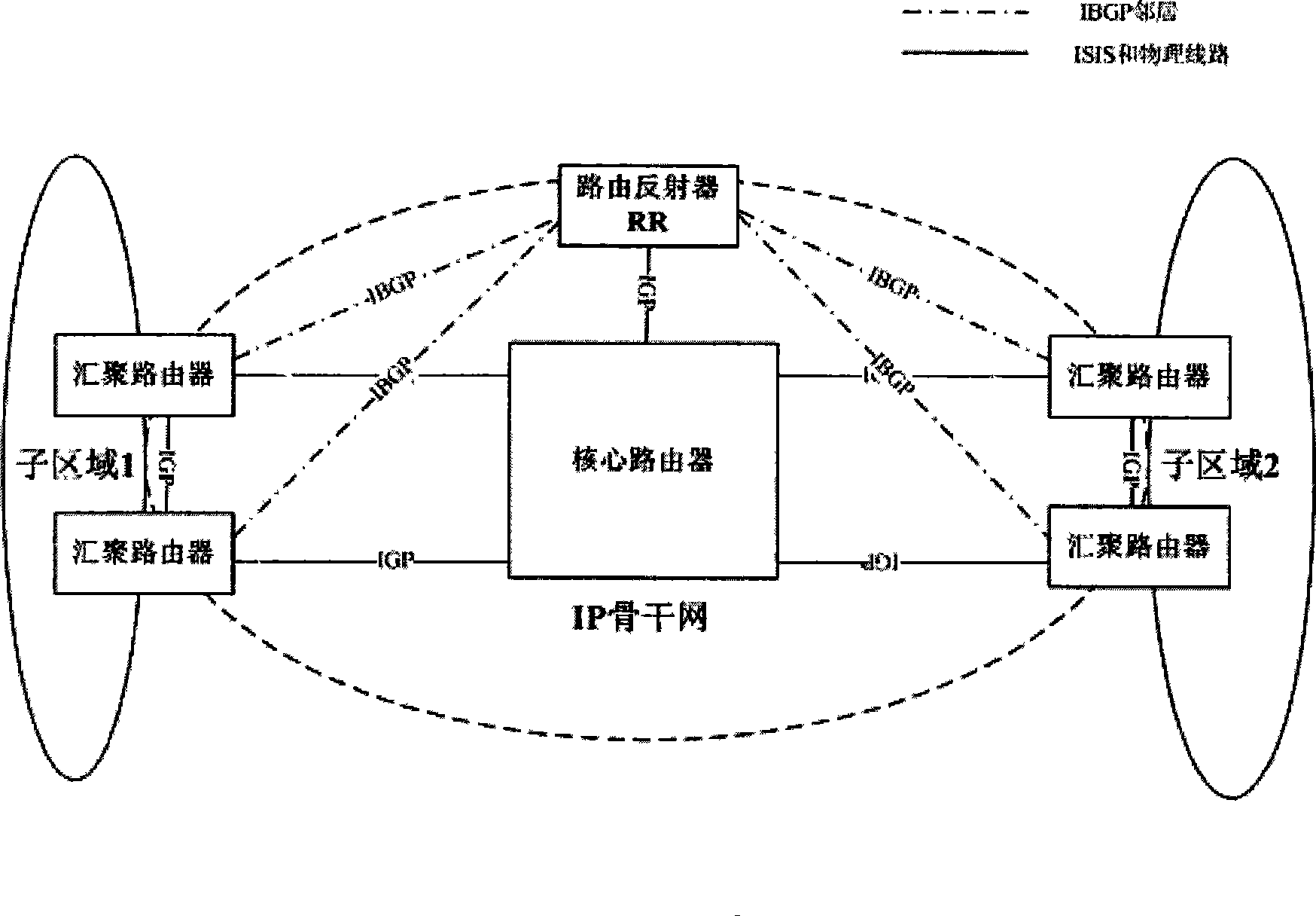
Technical field [0001] The invention relates to the field of data communication networks, and in particular to a method for balancing traffic load of an IP backbone network. Background technique [0002] The current IP backbone network can be divided into two levels, one is the data forwarding plane, and the other is the routing forwarding plane. The data forwarding plane is composed of network elements and physical lines between network elements. figure 1 Shows the most common network model of the current IP backbone network. For mutual access between sub-area 1 and sub-area 2, two aggregation routers are set up at the edge of the area on the basis of network redundancy. At the same time, a core router is set up in the backbone network to forward the mutual access traffic in the backbone network. The core router is fully connected with the aggregation routers in each sub-area. The network composed of convergence routers, core routers and the lines between them can be considered...

Claims


Application Information

Patent Timeline
Patent Type & Authority Applications(China)
IPC IPC(8): H04L12/56H04L12/46H04L29/06H04L12/803
Inventor 邓炜赵武范春湘
Owner CHINA MOBILE GRP GUANGDONG CO LTD
Learn More