Microphone manufacturing method

A manufacturing method and microphone technology, applied to electret electrostatic transducers, sensors, electrostatic transducer microphones, etc., can solve the problems of increasing the resistance of diaphragm vibration and affecting the sensitivity of microphones, and achieve good air tightness Effect

Inactive Publication Date: 2013-01-09
AAC ACOUSTIC TECH (SHENZHEN) CO LTD
View PDF6 Cites 0 Cited by
  • Summary
  • Abstract
  • Description
  • Claims
  • Application Information

AI Technical Summary

Problems solved by technology

In order to obtain a good sealing effect, the inside of the microphone is usually sealed with sealing glue. Since the glue is easy to flow and the sealing is too strong, it will easily form a closed cavity in the back cavity of the sound cavity inside the microphone, which increases the vibration of the diaphragm. resistance, which affects the sensitivity of the microphone

Method used


Image

  • Microphone manufacturing method
  • Microphone manufacturing method
  • Microphone manufacturing method

Examples


Embodiment Construction

[0020] The present invention will be further described below in conjunction with the accompanying drawings.

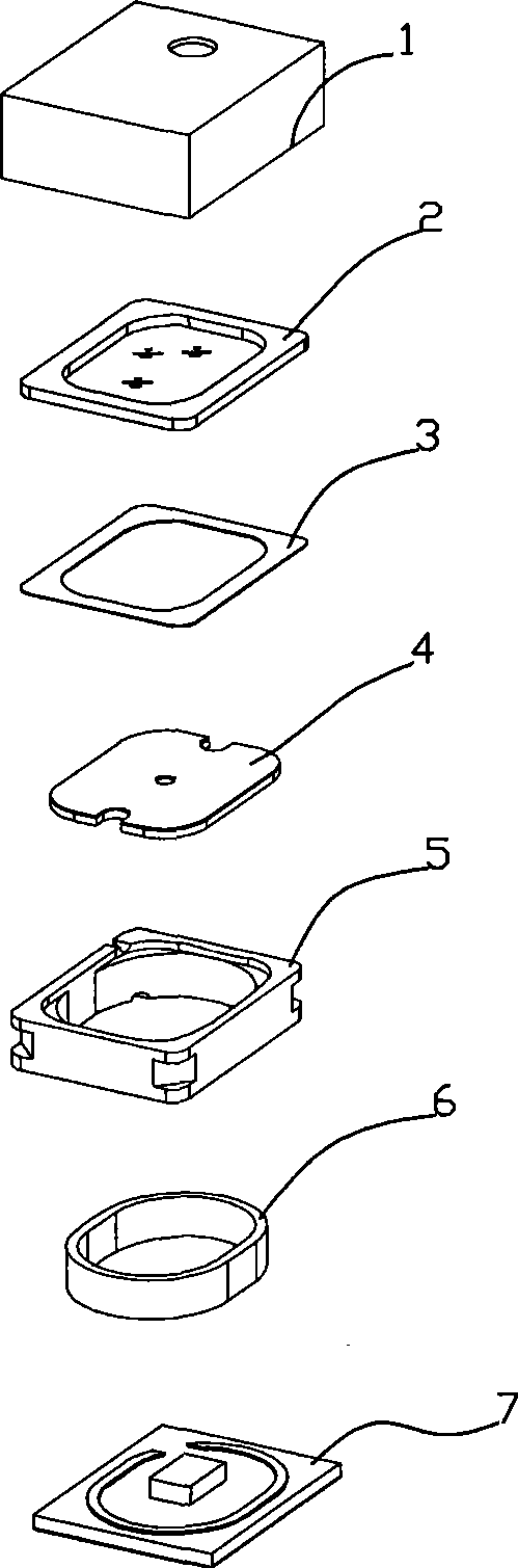
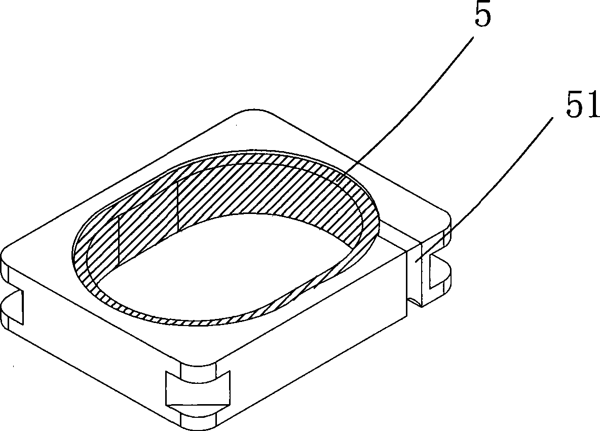
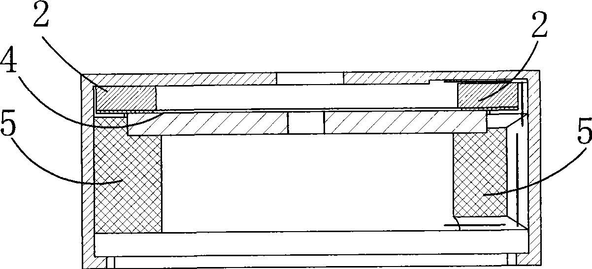
[0021] Such as figure 1 As shown, in an embodiment provided by the present invention, the microphone includes a housing 1, a diaphragm group 2 housed in the housing 1, a gasket 3 placed on the diaphragm group 2, and a back pole seat adjacent to the gasket 3 5. The back plate 4 embedded in the back plate 5 , the connection ring 6 connected with the back plate 4 , and the circuit board 7 electrically connected with the casing 1 . Wherein, the back pole plate 4 and the connecting ring 6 are accommodated in the back pole seat 5 respectively.

[0022] The housing 1 may take various shapes (eg cup-shaped, rectangular, D-shaped or trapezoidal-shaped). The housing 1 can be made of alternating layers of conductive and non-conductive material, or a conductive coating can be applied on the inside of the non-conductive layers, enabling the diaphragm pack 2 to be electrically con...


PUM


Abstract

The invention discloses a microphone manufacturing method, including the following steps: providing the necessary microphone shell, diaphragm groups, pads, a back pole seat, a back polar plate, a connecting ring and a circuit board of the microphone; assembling the diaphragm groups, the pads, the back pole seat, the back polar plate, the connecting ring and the circuit board in the microphone shell, wherein, the plane the back pole seat facing to the circuit board is higher than the plane the connecting ring facing to the circuit board; and packaging, squeezing the back pole seat to the direction of the pad when sealing the shell, the back pole seat ballooning to the shell in side direction after pressing, so that the plane the back pole seat facing to the circuit board is lower than the plane the connecting ring facing to the circuit board. Because the circuit board squeezes the back pole seat to the direction of the pad when sealing the shell, the back pole seat balloons to the shell in side direction after pressing, filling the gap between the back pole seat and the shell, so that the shell and the back pole seat housed in the shell are in an interference fit, so as to guarantee that the microphone has favorable air tightness.

Description

technical field [0001] The invention relates to a method for manufacturing a microphone. Background technique [0002] Mobile communication technology has developed rapidly in recent years. Consumers are increasingly using mobile communication devices such as cellular phones, Internet-capable cellular phones, personal digital assistants, laptop computers, laptop computers, graphics input cards, or other devices capable of communicating over public or private communication networks . The expansion of cellular networks and technological advancements in mobile communications have enabled more consumers to use mobile communications devices. [0003] Consumers' requirements for mobile communication equipment are not only satisfied with the ability to make calls, but also to be able to provide high-quality call effects. Especially with the development of mobile multimedia technology, the call quality of mobile phones is more important. Voice device, its design quality directly ...

Claims


Application Information

Patent Timeline
Patent Type & Authority Patents(China)
IPC IPC(8): H04R31/00H04R19/01H04R19/04
Inventor 周成军
Owner AAC ACOUSTIC TECH (SHENZHEN) CO LTD
Why Eureka
Try Eureka