Detachable connecting rod compressor having the same

A connecting rod and detachable technology, which is applied in the field of compressors, can solve problems such as complex assembly operations and achieve the effect of preventing distance changes

Active Publication Date: 2009-05-06
LG ELECTRONICS INC
View PDF1 Cites 9 Cited by
  • Summary
  • Abstract
  • Description
  • Claims
  • Application Information

AI Technical Summary

Problems solved by technology

[0010] exist figure 1 and 2 In the configuration shown in , the connecting rod 70 is integrally formed, and as a result, it is very complicated to perform an assembly operation of coupling the connecting rod 70 to the eccentric portion 51 of the crankshaft 50 and the piston 60, respectively.

Method used


Image

  • Detachable connecting rod compressor having the same
  • Detachable connecting rod compressor having the same
  • Detachable connecting rod compressor having the same

Examples


Embodiment Construction

[0040] Reference will now be made in detail to the preferred embodiments of the present invention, examples of which are illustrated in the accompanying drawings. It will also be apparent to those skilled in the art that various modifications and changes can be made in the present invention without departing from the spirit and scope of the invention. Thus, it is intended that the present invention covers the modifications and variations of this invention provided they come within the scope of the appended claims and their equivalents.

[0041] Referring to the following drawings, a detachable connecting rod and a compressor having the same will now be described in detail according to an embodiment of the present invention.

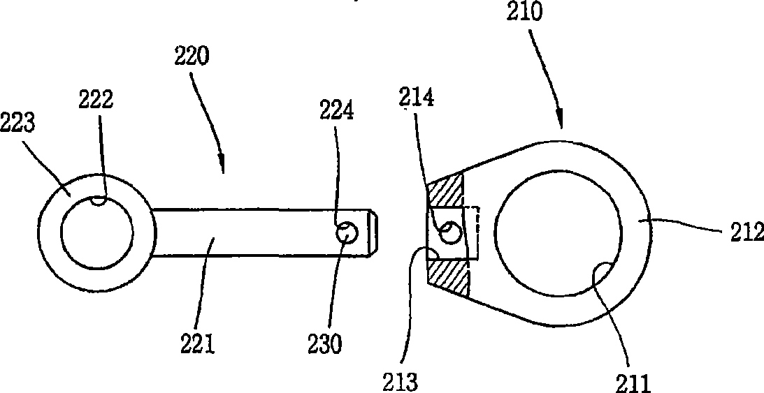
[0042] 5 and 6 are plan and front views showing a first embodiment of the detachable connecting rod according to the present invention.

[0043] As shown in FIGS. 5 and 6 , the detachable connecting rod 400 according to the present invention is composed ...


PUM


Abstract

A detachable connecting rod includes a first member including a large end portion having a through hole, and a first connection rod portion extending from the large end portion, the first connection rod portion having a pair of spaced apart arms defining a coupling groove extending in the same direction as an axial direction of the through hole; a second member including a small end portion having a through hole, and a second connection rod portion extending from the small end portion, the second connection rod portion being inserted into the coupling groove; and a coupling unit for coupling the first connection rod portion to the second connection rod portion inserted into the coupling groove of the first member. The detachable connecting rod is useable in a compressor.

Description

technical field [0001] The present invention relates to a compressor, and more particularly, to a detachable connecting rod capable of simplifying an assembly process and reliably connecting a crankshaft to a piston, and a compressor having the detachable connecting rod. Background technique [0002] Typically, a compressor converts electrical energy into kinetic energy and compresses a gas with the kinetic energy. According to the compression mechanism, the compressor includes a rotary compressor, a scroll compressor, a reciprocating compressor, and the like. [0003] figure 1 is a cross-sectional view showing an exemplary reciprocating compressor. Such as figure 1 As shown in , the reciprocating compressor includes: a housing 10; a driving motor M arranged in the housing 10 for generating rotational force; an elastic support unit 20 for elastically supporting the driving motor M on the housing 10 Frame F, which has cylinder 30 and is arranged on the upper part of drive...

Claims


Application Information

Patent Timeline
Patent Type & Authority Applications(China)
IPC IPC(8): F04B53/14F04B39/14
CPCF04B39/0022F16C2360/42Y10T74/2162Y10T74/2142F04B39/00F04B53/14
Inventor 朴垧俊裴智荣金镇国金范埈南赫李宗穆金钟赫金敬皓
Owner LG ELECTRONICS INC
Why Eureka
Try Eureka