

Unrolling device for winders
A technology of uncoiling device and coil material, which is applied in the direction of coiling strip, transportation and packaging, function indication, etc., which can solve the problem of troublesome driving device of uncoiling device and achieve the effect of simple structure
- Summary
- Abstract
- Description
- Claims
- Application Information
AI Technical Summary
Problems solved by technology
Method used
Image

Examples
Embodiment Construction
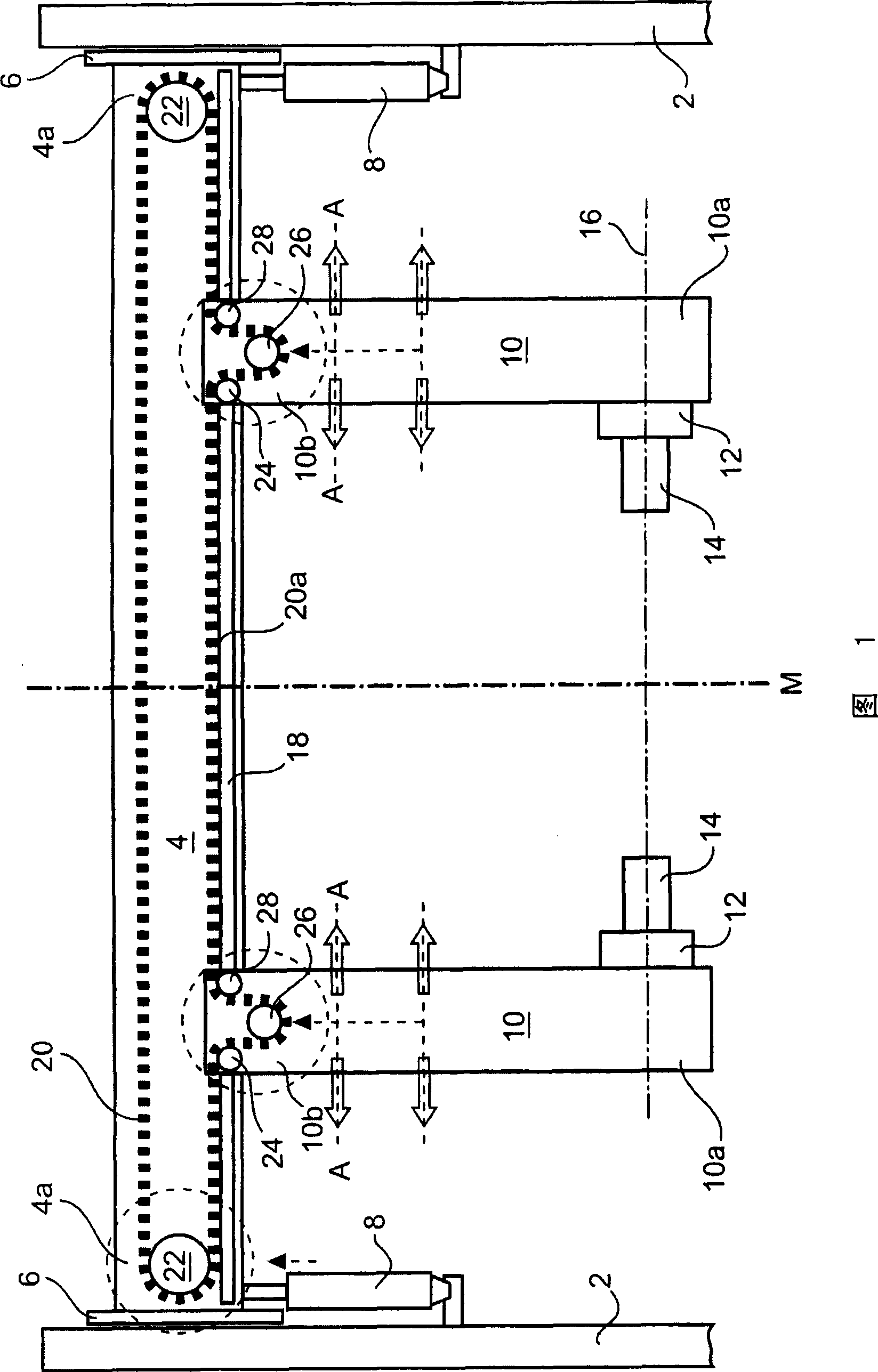
[0028] The preferred embodiment of the device for unwinding a wound web, schematically illustrated in FIG. 1, is preferably used in the paper processing industry for the paper web to be pulled out from a wound web for further processing, and it has a frame in which The figure shows only partially schematically two spaced apart vertical columns 2 . Usually four such vertical uprights are used to form the machine frame, which are connected to one another by longitudinal and transverse beams, also not shown in the figures.
[0029] As shown in the figure, a transverse beam 4 is arranged between two spaced apart vertical columns 2, which extends substantially horizontally. The crossbeam 4 is supported vertically displaceably in the illustrated embodiment on the columns 2 via its two lateral ends 4a, wherein in the illustrated embodiment the support is via a guide rail acting in the vertical direction The system configuration is shown schematically in the drawing and indicated by ...
PUM
 Abstract
Description
Claims
Application Information