
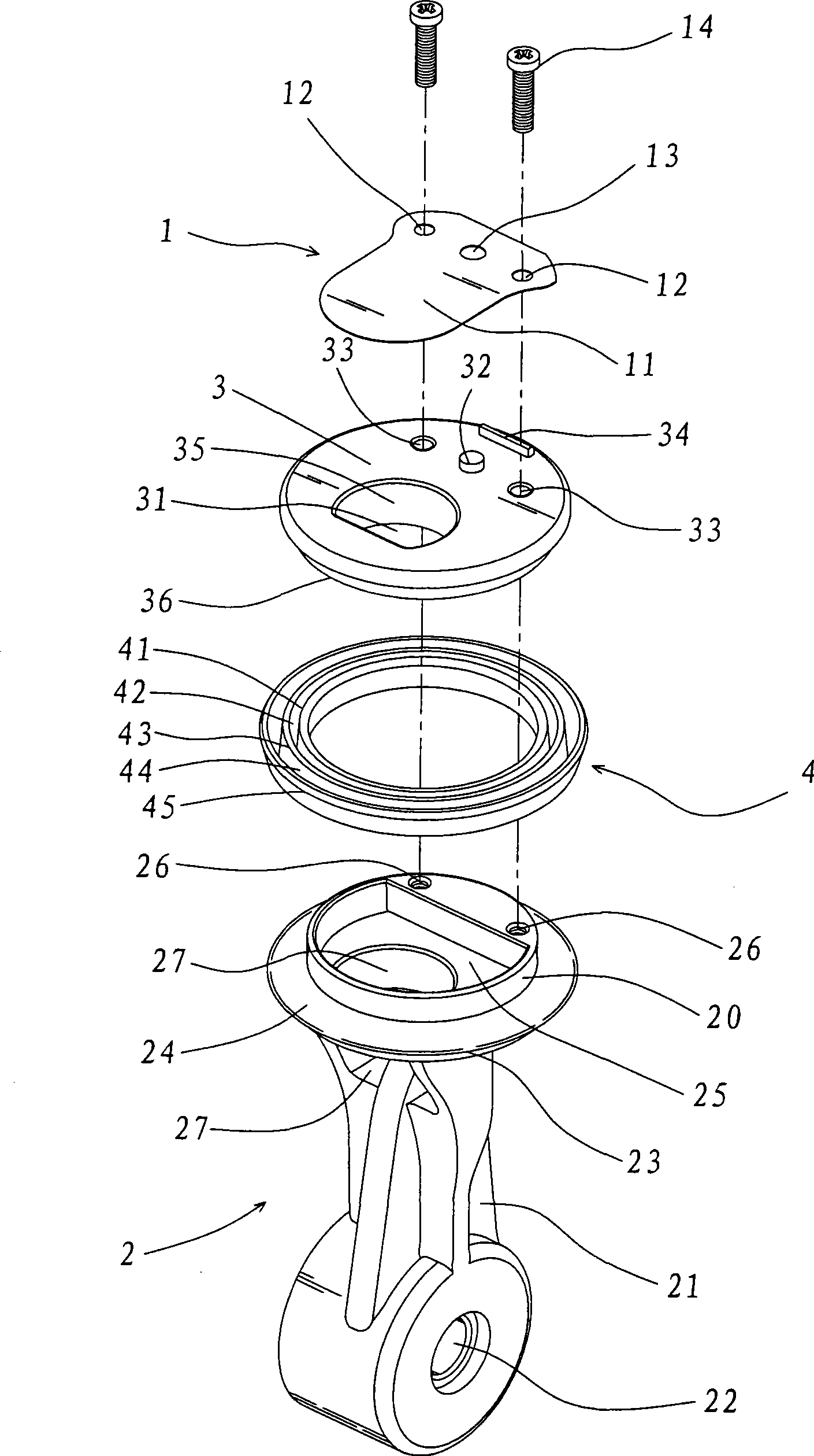
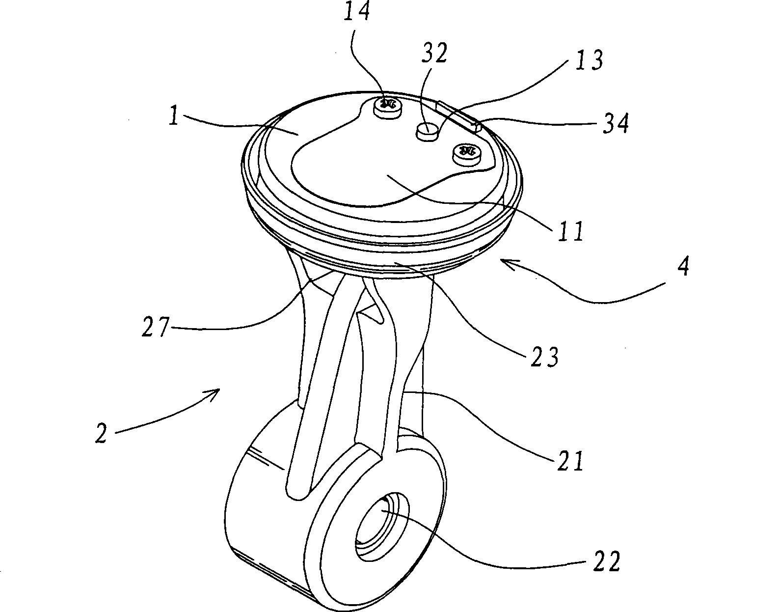
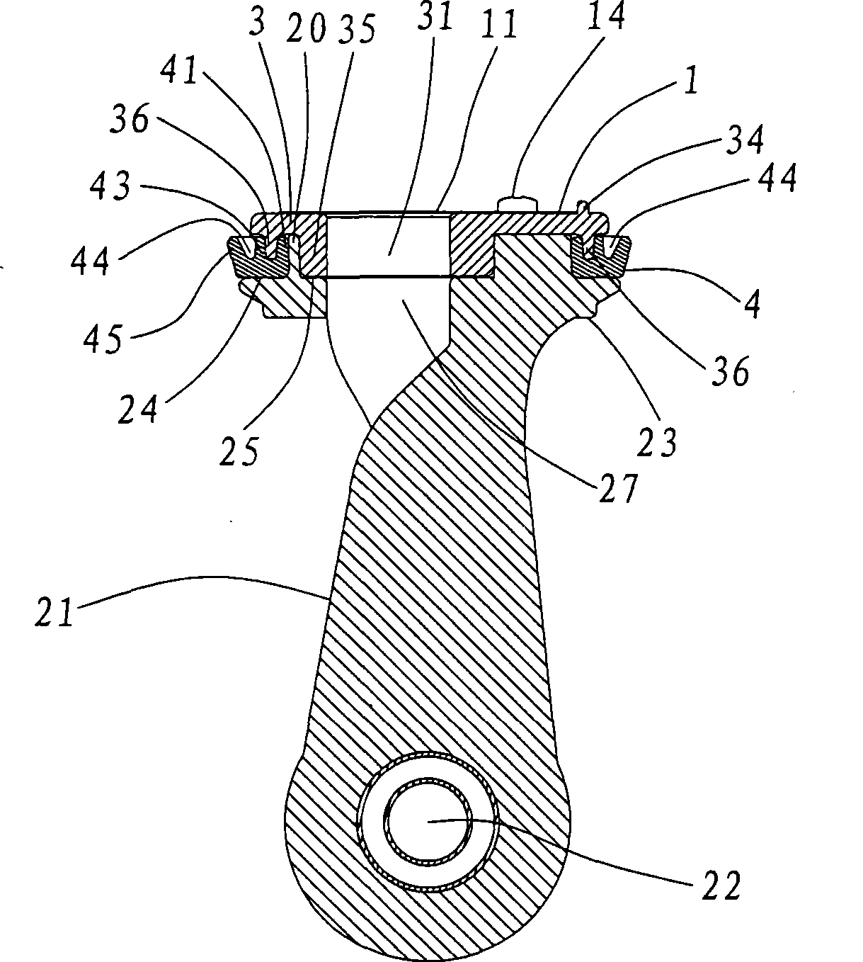
Piston body structure of air compressor

An air compressor and piston body technology, applied in the field of air compressors, can solve the problems of oil seal ring wear, resistance, deformation and bending of the fixed end, etc., and achieve the effect of good air tightness

Active Publication Date: 2009-05-13
周文三
View PDF0 Cites 4 Cited by
  • Summary
  • Abstract
  • Description
  • Claims
  • Application Information

AI Technical Summary

Problems solved by technology

[0002]The piston body commonly used in air compressors, its main structure is that a passage connecting up and down is provided on the valve head of the piston body, and an elastic metal valve plate One end is fixed on the valve head, and the other parts are completely closed on the channel. When the piston body reciprocates in the cylinder chamber, the valve plate will be opened and closed at high frequency times, so that the fixed end of the valve plate will bear the maximum load. Stress, because the stress on the top plane of the valve head generated by the valve plate during the opening and closing action often easily causes the fixed end to deform and bend, so that the valve plate cannot form an airtight effect on the channel, and loses the compression function of the air compressor
On the other hand, it is known that the piston body is provided with an O-type oil seal ring on the periphery of its valve head. Since the O-type oil seal ring cannot produce better airtight deformation with the reciprocating motion of the piston body, it is not only easy to After long-term use, the oil seal ring is prone to wear and tear, and even breaks, and the airtight effect of compressed air cannot be achieved.

Method used


Image

  • Piston body structure of air compressor
  • Piston body structure of air compressor
  • Piston body structure of air compressor

Examples


Embodiment Construction

[0040] Please refer to Figure 10 to Figure 12 , which is a schematic diagram of an air compressor. A motor 7 is installed behind the base 5. The small gear 71 at the front of the motor 7 is meshed with a large gear 72. The large gear 72 is stacked with a counterweight 74 and combined with a The shaft 73 is pivotally connected to the base 5 , and the counterweight 74 is provided with an eccentric tip 75 pivotally connected to the shaft hole 22 of the piston body 2 . When the motor 7 rotates, the small gear 71 in front of the motor 7 rotates the large gear 72 and the counterweight 74, and the eccentric pin 75 on the counterweight 74 rotates the piston body 2 so that the valve head 23 of the piston body 2 is in the compression cylinder 6 Do repeated movements, so air is transported into the air collection seat 61 and then diverted to the devices installed in the manifolds 62, 63, 64, 65 and flexible pipes 641, 651, such as the barometer 8, the air nozzle 9, the deflated Valve b...


PUM


Abstract

The invention relates to a piston body structure for an air compressor, wherein an oil seal ring which is provided with two circular grooves is arranged on a valve head of a piston body, and a valve plate capable of dispersing stress is arranged on an upper cover body of the piston body, so that the vibratory stress energy is uniformly dispersed when the valve head is beaten by the valve plate and the phenomenon of incapability of realizing airtight seal due to loss of uneasy stress concentration and crease on a neck section or a fixed section of the piston body can not be generated; and due to actuation of the oil seal ring provided with the two circular grooves along with the piston body when the piston body is actuated inside a compression cylinder, better airtight effect is formed between the piston body and the inner wall of the compression cylinder.

Description

technical field [0001] The invention relates to an air compressor, in particular to a piston body structure of the air compressor, which can form a better airtight effect between the piston body and the inner wall of the compression cylinder. Background technique [0002] The main structure of the known piston body used in air compressors is that there is a channel connected up and down at the valve head of the piston body, and one end of an elastic metal valve plate is fixed on the valve head, and the other parts are completely closed on the channel. , when the piston body reciprocates in the cylinder chamber, the valve plate will be opened and closed at a high frequency, so that the fixed end of the valve plate will bear the maximum stress. The stress on the top plane often easily causes the fixed end to deform and bend, which makes the valve plate unable to form an airtight effect on the channel and loses the compression function of the air compressor. On the other hand,...

Claims


Application Information

Patent Timeline
IPC IPC(8): F04B39/00
Inventor 周文三
Owner 周文三
Learn More