Position indication apparatus for valve body movable sealing ring

A technology of dynamic sealing ring and indicating device, which is applied to valve device, cock including cut-off device, lift valve, etc. The valve body dynamic sealing ring indicating device is not suitable for installation, etc.

Inactive Publication Date: 2009-05-13
TIELING VALVE
View PDF1 Cites 5 Cited by
  • Summary
  • Abstract
  • Description
  • Claims
  • Application Information

AI Technical Summary

Problems solved by technology

[0005] This kind of valve body dynamic sealing ring indicator device uses a lever to transmit the movement of the valve body dynamic sealing ring. , the lever is in the elbow at the upper end of the circular tubular shell, and the elbow communicates with the inner cavity of the valve. When in use, the liquid medium in the inner cavity of the valve will enter the elbow. If the liquid medium contains impurities such as sediment, Impurities such as sediment will enter the elbow of the indicating device and deposit down. The sediment and other impurities deposited in the elbow will affect the swinging movement of the lever, not only cannot correctly indicate the switch state of the dynamic sealing ring of the valve body, but will Hinder the movement of the dynamic sealing ring of the valve body
This butterfly valve body dynamic sealing ring indicator device is not suitable for installation on valves conveying liquid media containing impurities such as sediment

Method used


Image

  • Position indication apparatus for valve body movable sealing ring
  • Position indication apparatus for valve body movable sealing ring
  • Position indication apparatus for valve body movable sealing ring

Examples


Embodiment Construction

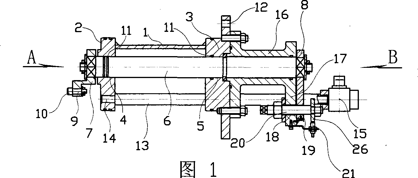
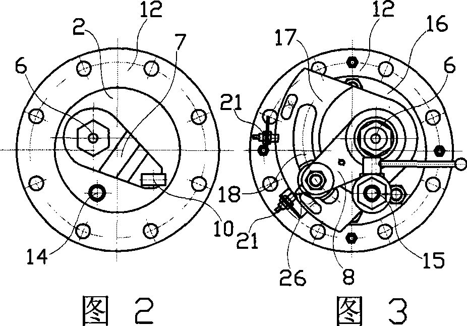
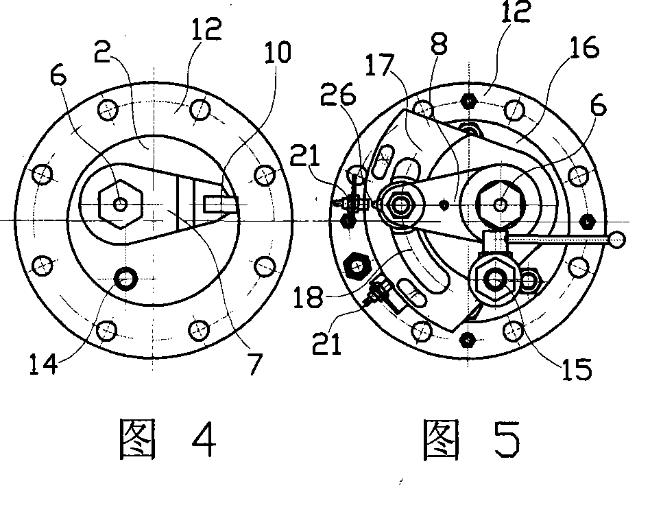
[0025] In Figures 1 to 5, the position indicating device for the dynamic sealing ring of the valve body has a circular tubular shell 1, and the front and rear ends of the circular tubular shell have front and rear end covers 2 and 3 respectively, and the two ends There are shaft holes 4 and 5 with axes on the same straight line on the cover respectively, and through shafts 6 are pierced in the shaft holes, and the front and rear ends of the through shafts are respectively connected with front and rear rocker arms 7 and 8 perpendicular to the through shafts. The outer end of the front rocker arm has a short shaft 9 parallel to the through shaft, a slider 10 is hinged on the short shaft, a sealing pair 11 is arranged between the through shaft and the end cover, and the rear end cover has a valve for fixing the device to the valve. Connect pad 12.

[0026] When the present invention is installed on the valve for use, impurities such as sediment in the liquid medium will not enter...


PUM


Abstract

A position indicating device of a valve body dynamic sealing ring is provided with a circular tube shell provided with a front end cover and a rear end cover, a communicating shaft which passes through the front and the rear end covers and is respectively connected with a front rocker arm and a rear rocker arm at the two ends, a sliding block articulated at the outer end of the front rocker arm, a flushing pipe that is connected between the front end cover and the rear end cover, a short circular tube that is provided with a radial support saddle at the rear end and is connected with the rear end cover, a cambered long narrow hole arranged on the support saddle, a round orifice arranged at the outer end of the rear rocker arm, a threaded rod connected between the cambered long narrow hole and the round orifice arranged at the outer end of the rear rocker arm, and a proximity switch that is arranged between the outer end of the rear rocker arm and the support saddle and is respectively corresponding to the on and the off states of the valve body dynamic sealing ring. The position indicating device uses the communicating shaft which is respectively connected with rocker arms at the two ends for transmitting the movement of the valve body dynamic sealing ring, the communicating shaft is arranged in the circular tube shell that is installed in a mounting hole of the valve body, and sealing pairs are respectively arranged between the communicating shaft and the shell and between the shell and the mounting hole; when in use, impurities such as silt and the like in liquid medium can not enter the shell, so that the accurate indication of combination and separation between valve body dynamic sealing ring and a butterfly plate sealing ring is not influenced.

Description

technical field [0001] The invention relates to a valve body dynamic sealing ring indicating device of a butterfly valve or a ball valve, in particular to a transmission mechanism of the valve body dynamic sealing ring indicating device of a butterfly valve or a ball valve. Background technique [0002] Butterfly valves or ball valves are valves that open and close the valve by rotating the spool 90 degrees. When the butterfly valve or ball valve is turned 90 degrees to switch, friction occurs between the butterfly plate sealing ring and the valve body sealing ring due to the sealing specific pressure. The greater the sealing specific pressure, the better the sealing performance, but when the butterfly valve or ball valve is switched The greater the friction between the sealing surfaces of the valve body, the friction of the butterfly valve or ball valve when switching will cause wear and scratches on the butterfly plate sealing ring and the valve body sealing ring, and the ...

Claims


Application Information

Patent Timeline
Patent Type & Authority Applications(China)
IPC IPC(8): F16K37/00F16K1/32F16K1/228F16K5/08F16K5/06
Inventor 李振春刘丽华
Owner TIELING VALVE
Why Eureka
Try Eureka