Means for preventing tools from being pulled out from tool holders with a tool holding fixture

A technology of clamping device and receiving part, which is applied in the direction of fixing the grinding wheel, the attachment of the tool holder, the connection of the tool and the workpiece, etc., which can solve the problems of inaccuracy, danger of machine operators, dangerous accidents, etc., and achieve less waste and cost saving Effect

Active Publication Date: 2009-05-13
FRANZ HAIMER MASCHINENBAU KG
View PDF1 Cites 20 Cited by
  • Summary
  • Abstract
  • Description
  • Claims
  • Application Information

AI Technical Summary

Problems solved by technology

Due to this unfavorable effect, workpieces cannot be machined precisely and to size specifications
In addition, twisting of the rotating tool in the workpiece or even in the clamping disk receiving the workpiece can lead to dang

Method used


Image

  • Means for preventing tools from being pulled out from tool holders with a tool holding fixture
  • Means for preventing tools from being pulled out from tool holders with a tool holding fixture
  • Means for preventing tools from being pulled out from tool holders with a tool holding fixture

Examples


Embodiment Construction

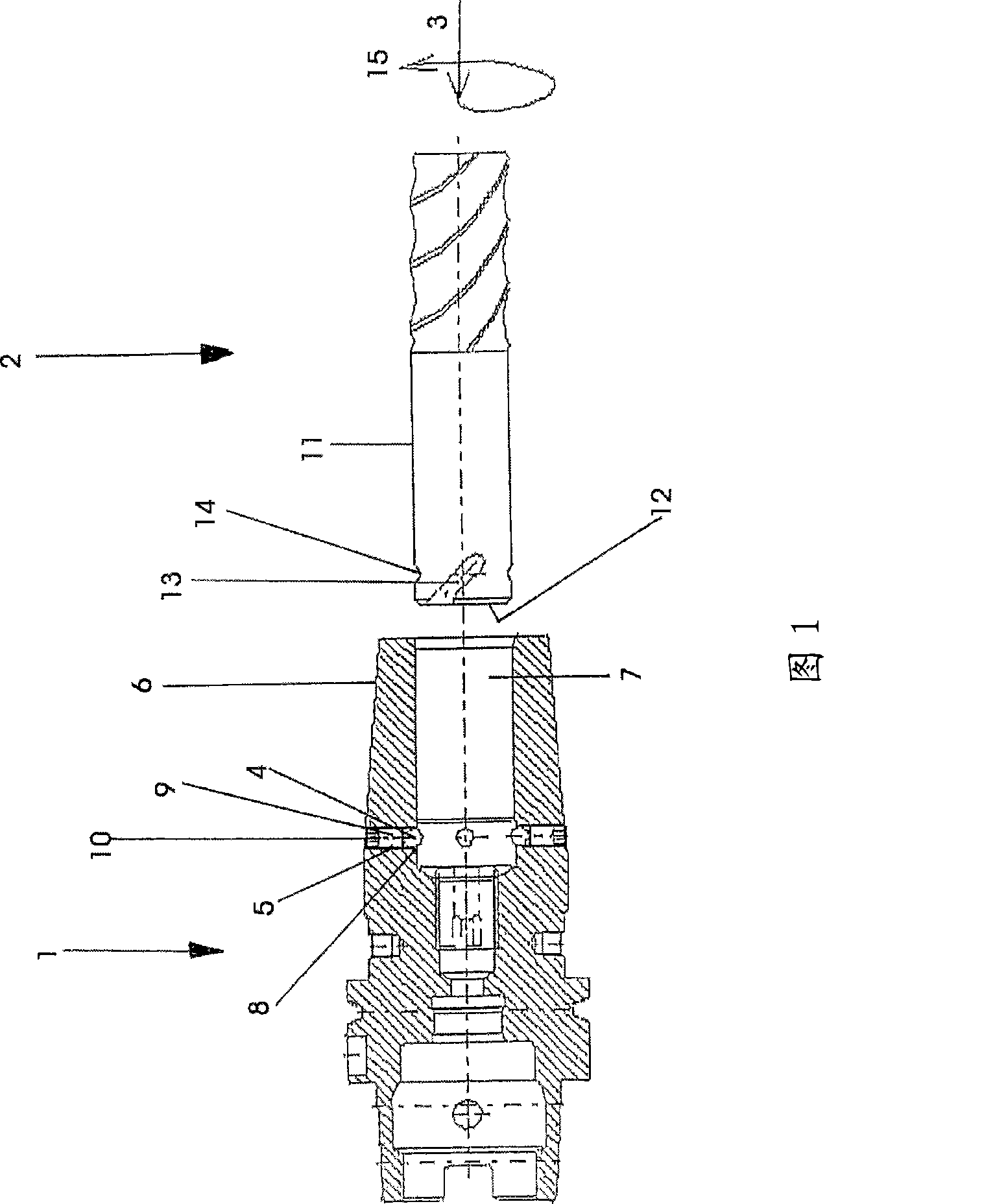
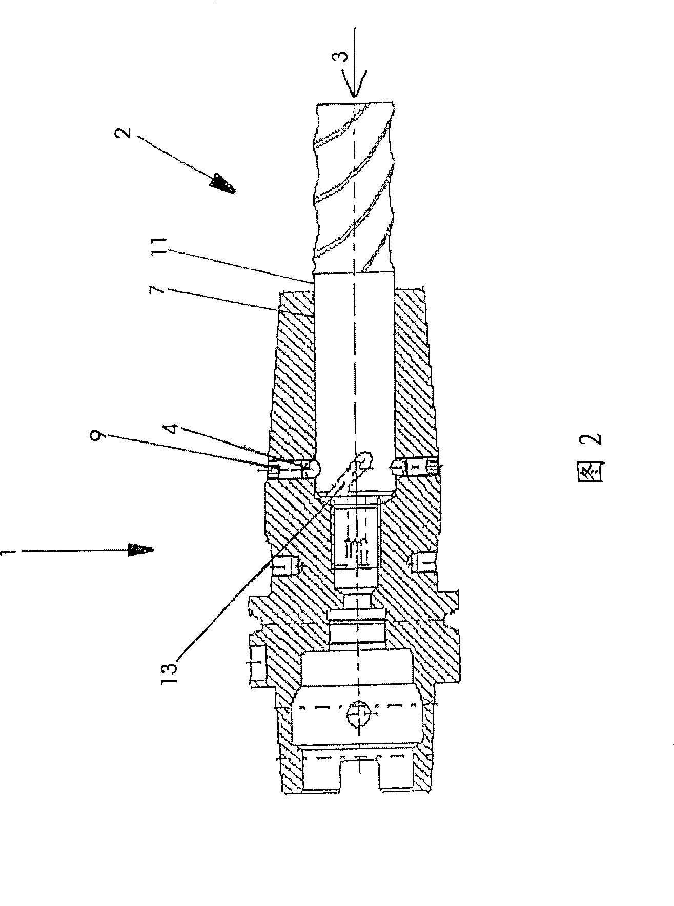
[0042] FIG. 1 schematically shows a sectional view of a tool holding device 1 and, by way of example, an end mill 2 , which are arranged relative to one another with respect to an axis of rotation 3 . The tool holding device 1 here has at least two, preferably three or four balls 4 . The ball is located here in a bearing bore 5 which is perpendicular to the axis of rotation 3 and thus to the longitudinal axis of the sleeve section 6 of the tool holding device 1 . The bearing hole 5 is a through hole and extends from the sleeve section 6 to the inner circumference of a receiving opening 7 which is arranged concentrically to the axis of rotation 3 in the tool holding device 1 . The front bearing side 8 of the bearing bore 5 is formed in the form of a spherical cap and corresponds to the spherical shape of the ball 4 , so that the ball 4 projects partially into the interior of the receiving opening 7 . The ball 4 is held by a threaded pin 9 in its frontal position, i.e. in a pos...


PUM


Abstract

The present invention relates to a cutter holding device which is provided with a cutter receiving part, especially a clamping disc, such as a thermal shrinking chuck, a nipper chuck, a hydraulic expanding chuck and a high-precision chuck. The handle of cutter, especially the handle of rotating cutter is accommodated in the cutter receiving part, wherein the cutter holding device comprises a pulling-out preventing fixing device which fixes the cutter and prevents the axial pulling-out. The pulling-out preventing device comprises at least one fixing component and at least one fixing groove which is corresponding with the fixing component and accommodates the fixing component. The fixing component cooperates with the fixing groove with a mode of forming locking. According to the invention, the fixing component and the fixing groove are all designed to at least partial sphere-head shaped. Preferably the cutter is provided with the locking groove. As the fixing groove is preferably spirally rotating along the cylindrical handle of cutter, the rotation direction is corresponding with the slotting direction of cutter, and axial fixing can be executed to the cutter. Thereby the cutter will not be axially pulled out from the cutter holding device in the running period. A component for exerting force is additionally installed. The component forms a gapless attachment on the pulling-out preventing fixing device after shrinking and installation.

Description

technical field [0001] The invention relates to a tool holding device according to the preamble of claim 1 with a tool receptacle, in particular a shrink chuck or other chuck for receiving a rotating tool. Background technique [0002] Various forms of tool holding devices with chucks, in particular shrink chucks, are known. The tool holding device is used for clamping tubular tools, turning tools, milling tools, reaming tools, grinding tools etc. by means of thermally induced shrinkage processes. Usually such shrink chucks are heated thermally by means of an induction shrinking device, whereby the inner diameter of the shrink chuck expands. When the inner diameter is enlarged, put the tool to be clamped into the heat-shrinkable chuck, and at the same time, the ratio of the inner diameter of the heat-shrinkable chuck to the shank diameter of the tool is designed so that after the heat-shrinkable chuck cools down, the tool Clamped against torque by shrink chucks. [0003] ...

Claims


Application Information

Patent Timeline
IPC IPC(8): B23B31/107B23B31/117B23B31/20
CPCB23B31/1175B23B31/40B23B31/1071B23B2231/026B23B2231/04B23B2260/042B23B2260/138B23B31/10B23B31/1179B23B31/005B23B2240/04B23B31/1072B24B45/006Y10T408/907Y10T409/30952Y10T279/17Y10T279/1021Y10T279/17923Y10T279/17888Y10T279/17897Y10T408/95Y10T408/94Y10T279/17316
Inventor 弗朗茨·海默尔
Owner FRANZ HAIMER MASCHINENBAU KG
Why Eureka
Try Eureka