Draining device of extracting tube

A liquid discharge device and extraction tube technology, applied in the direction of solid solvent extraction, etc., can solve the problems of low liquid level in the extraction tube, overflow of solvent, easy blockage of the liquid discharge tube, etc., and achieve the goals of preventing discharge, prolonging contact, and reducing slag content Effect

Active Publication Date: 2009-05-20
JINING SINOBEST BIOLOGICAL MACHINERY
View PDF4 Cites 7 Cited by
  • Summary
  • Abstract
  • Description
  • Claims
  • Application Information

AI Technical Summary

Problems solved by technology

[0002] In the prior art, the known technology is to drain the liquid at the bottom or middle of one end of the extraction pipe. The problem with this liquid drainage method is that the extraction liquid contains a large amount of slag, which not only easily blocks the liquid discharge pipe, but also causes It is difficult to filter in the next step, and at the same time, it is difficult to control the flow rate of the liquid discharge. A small flow rate will easily cause the solvent entering the extraction tube to overflow from the liquid inlet part, and a high flow rate will easily cause the liquid level in the extraction tube to be too low and affect the extraction effect. the shortcomings of the existing technology

Method used


Image

  • Draining device of extracting tube
  • Draining device of extracting tube

Examples


Embodiment Construction

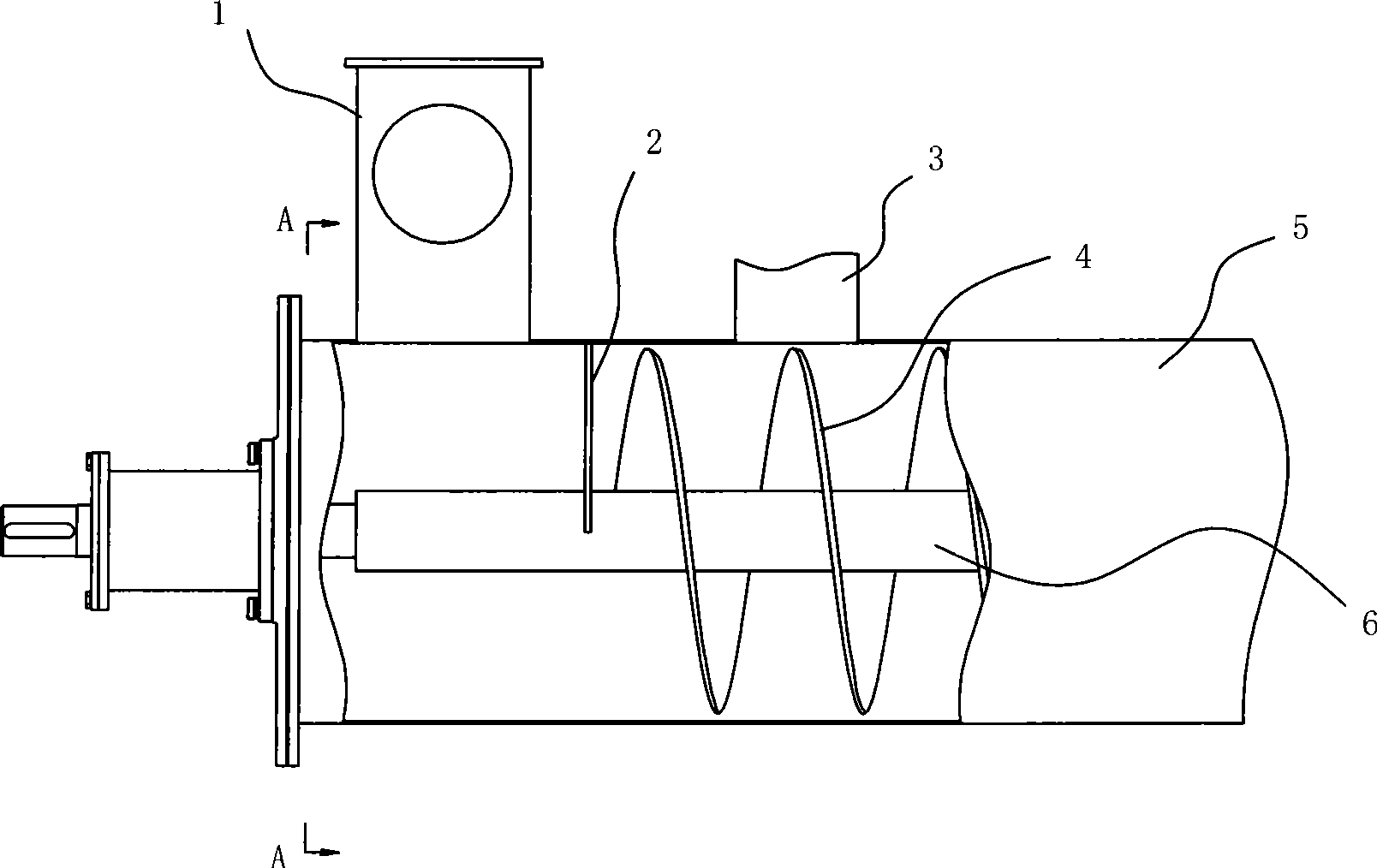
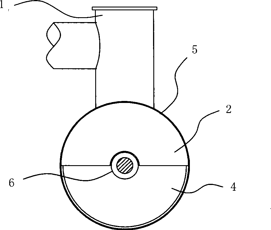
[0009] In order to clearly illustrate the technical features of the solution, the solution will be described below through a specific implementation mode combined with the accompanying drawings.

[0010] As can be seen from the accompanying drawings, the liquid discharge device of the extraction tube of this program has an extraction tube 5 and a screw propeller composed of a propulsion shaft 6 and a helical blade 4 fixed on the propulsion shaft 6 in the extraction tube 5. One end of 5 has feed pipe 3, and this scheme has liquid outlet pipe 1 on the top of extraction pipe 5 between described extraction pipe 5 side end and feed pipe 3, and the upper part liquid pipe of extraction pipe 5 lumens A baffle plate 2 is fixed between the feed pipe 1 and the feed pipe 3, and the baffle plate 2 is located at the end of the spiral blade 4. The material baffle plate 2 is semicircular fan-shaped, and the arc at the upper end of the material baffle plate 2 is the same as the inner cavity ra...


PUM


Abstract

The invention provides horizontal pipeline extraction equipment for extracting solid materials by utilization of a solvent, and in particular relates to a technical proposal of a draining device for a reverse-flow extraction pipe. The proposal comprises the extraction pipe and a screw propeller which is arranged inside the extraction pipe and consists of a propulsion shaft and a spiral blade which is fixed on the propulsion shaft, wherein a feeding pipe is arranged on one end of the extraction pipe. The proposal is characterized in that a drain pipe is arranged on the upper top of the extraction pipe between the side end of the extraction pipe and the feeding pipe; a retaining plate is fixed between the upper drain pipe of an inner cavity of the extraction pipe and the feeding pipe and positioned on the end part of the spiral blade, and is a semicircular sector; and the upper edge of the retaining plate is closely connected with the inner cavity of the extraction pipe.

Description

Technical field: [0001] The invention relates to horizontally placed pipe-type extraction equipment, in particular to a liquid discharge device for an extraction pipe in which the material advancing direction is opposite to the extraction medium flow direction. Background technique: [0002] In the prior art, the known technology is to drain the liquid at the bottom or the middle of one end of the extraction pipe. The problem with this liquid drainage method is that the extraction liquid contains a large amount of slag, which not only easily blocks the liquid discharge pipe, but also causes It is difficult to filter in the next step, and at the same time, it is difficult to control the flow rate of the liquid discharge. A small flow rate will easily cause the solvent entering the extraction tube to overflow from the liquid inlet part, and a high flow rate will easily cause the liquid level in the extraction tube to be too low, affecting the extraction effect. It is the weak ...

Claims


Application Information

Patent Timeline
Patent Type & Authority Applications(China)
IPC IPC(8): B01D11/02
Inventor 白中明
Owner JINING SINOBEST BIOLOGICAL MACHINERY
Why Eureka
Try Eureka