Liquid level control valve

A liquid level control, two-position three-way valve technology, applied in multi-way valves, valve devices, valve details, etc., can solve problems such as clogging of moving parts in water, sensors or liquid level switches requiring power supply, etc., to achieve liquid level The effect of control, simple structure and convenient adjustment

Active Publication Date: 2009-05-20
HUAZHONG UNIV OF SCI & TECH
View PDF2 Cites 18 Cited by
  • Summary
  • Abstract
  • Description
  • Claims
  • Application Information

AI Technical Summary

Problems solved by technology

[0003] The invention provides a liquid level control valve, which overcomes the problem that the existing liquid level con

Method used


Image

  • Liquid level control valve
  • Liquid level control valve
  • Liquid level control valve

Examples


Embodiment Construction

[0015] The present invention will be further described below in conjunction with the accompanying drawings and embodiments.

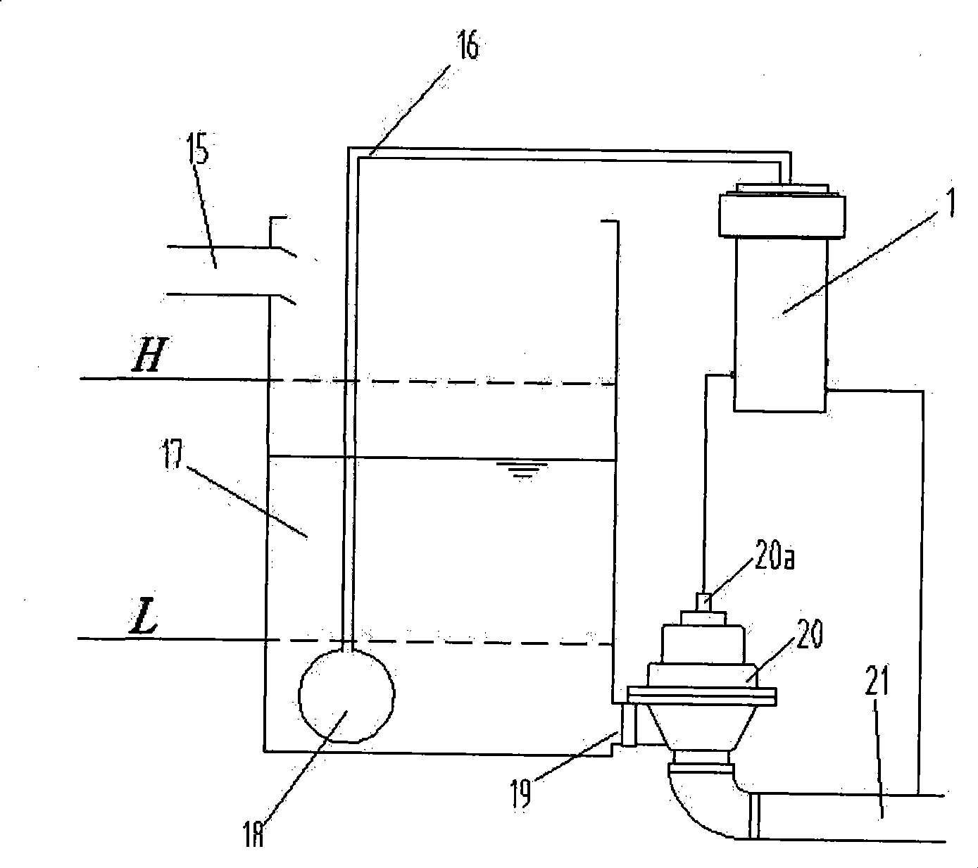
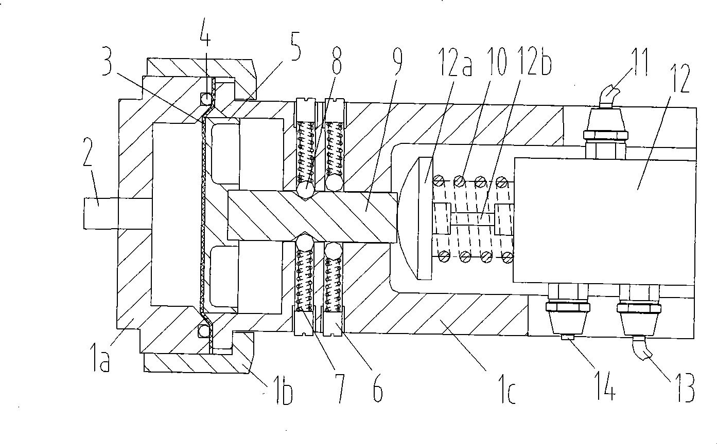
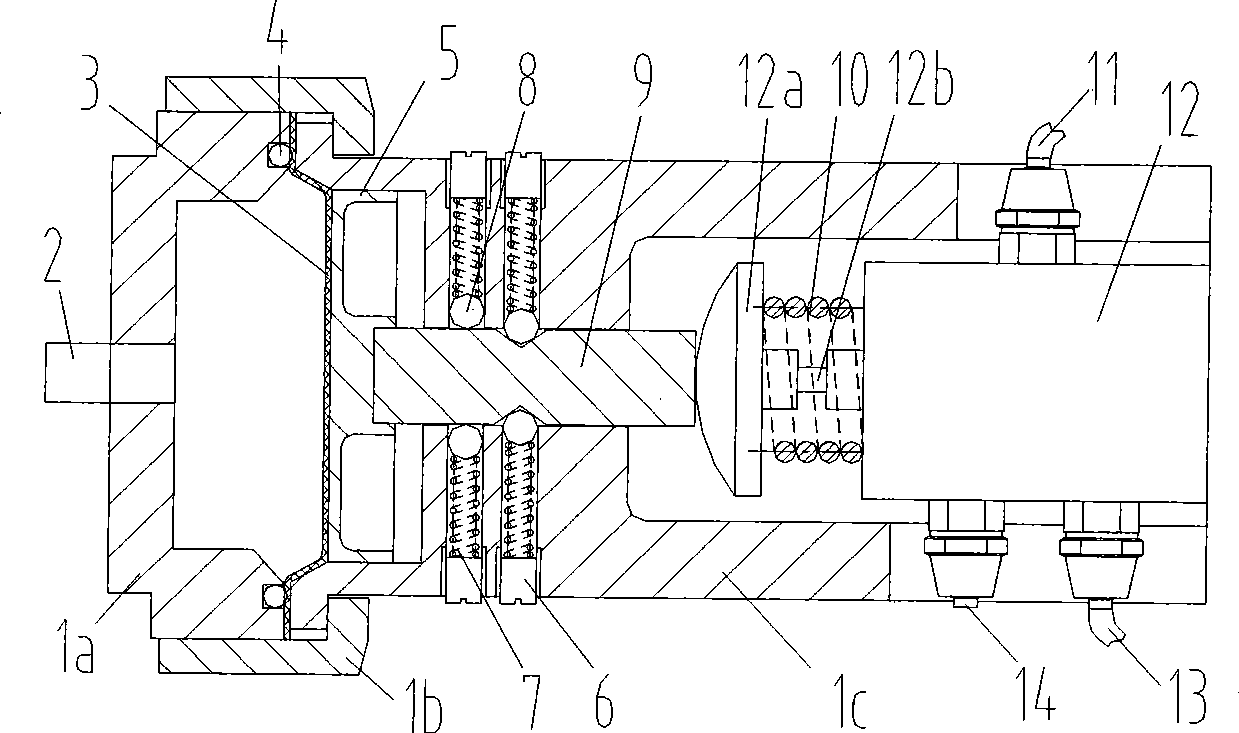
[0016] Such as figure 1 , figure 2 As shown, the water collection tank 17 collects and stores the sewage discharged by the user, the water collection tank inlet 15 is connected to the user's sewer pipe, the water collection tank outlet 19 is connected to the vacuum interface valve 20, and the air bag 18 is placed at the bottom of the water collection tank; the liquid level control valve 1 passes the liquid level sensor The pipe 16 communicates with the air bag 18, the interface valve joint 11 of the liquid level control valve 1 is connected to the interface valve control hole 20a, and the air source joint 13 is connected to the vacuum drainage pipe 21; the vacuum interface valve 20 is a normally closed negative pressure pneumatic valve, and its control hole 20a The vacuum interface valve 20 is opened when the negative pressure is connected, and the va...


PUM


Abstract

The invention provides a liquid level control valve, which belongs to a membrane type pressure valve, overcomes the problem that a sensor or a liquid level switch adopted by the prior liquid level control valve requires power supply, and avoids blockage of a movable part in water. One end of the valve body presses a membrane by a valve bonnet and a movable joint which are connected by threads; the membrane is closely attached with a baffle in the valve body; a liquid level inductive pipe union is arranged in the center of the valve bonnet; the other end of the valve body is provided with a two-position three-way valve; a valve core of the two-position three-way valve sleeved with a return spring is in threaded connection with a top cap; a groove is arranged on the surface in the middle of the valve core; one end of the valve core is embedded in the center of the baffle, and the other end of the valve core is contacted with the top cap; the position of the valve body corresponding to the groove of the valve is provided with four threaded holes of which every two are opposite; and a ball bearing and a spring are arranged in each threaded hole, and are limited by a regulating nut. The liquid level control valve has a simple structure, is convenient for regulating, can be opened or closed according to difference of the liquid level, and is particularly applicable to a vacuum drainage system which uses electric power supply, has more impurities in the water, and easily causes blockage of the movable part.

Description

technical field [0001] The invention belongs to a diaphragm type pressure valve, in particular to a liquid level control valve used in a vacuum drainage system. Background technique [0002] At present, the commonly used liquid level control method is to use pressure, resistance, capacitance or ultrasonic sensors or liquid level switches to contact the sensor or liquid level switch with the controlled liquid, and the sensor or liquid level switch will indicate the start or stop of drainage through electrical signals. The vacuum drainage system requires its liquid level control valve to achieve liquid level control without external power supply, and not to be disturbed or blocked by impurities in the sewage. There are many kinds of current liquid level control valves, such as the utility model patent of patent application number CN98251788.2 and announcement number CN2356082, which discloses a water-saving control device for an electro-hydraulic closet, which is composed of a...

Claims


Application Information

Patent Timeline
IPC IPC(8): F16K31/126F16K11/02F16K21/12F16K21/16
Inventor 周敬宣阳国柱李旻
Owner HUAZHONG UNIV OF SCI & TECH
Why Eureka
Try Eureka