Multi-channel spectral measuring device and phase difference analysis method

A multi-channel, measurement technology, applied in the field of spectrum measurement and calibration analysis, can solve problems such as measurement speed limitations, and achieve the effect of improving competitiveness and increasing measurement efficiency

Inactive Publication Date: 2009-05-20
IND TECH RES INST
View PDF1 Cites 10 Cited by
  • Summary
  • Abstract
  • Description
  • Claims
  • Application Information

AI Technical Summary

Problems solved by technology

In the traditional measurement method, in order to obtain the normalization of the measured intensity signal and calculate the phase difference value, it

Method used


Image

  • Multi-channel spectral measuring device and phase difference analysis method
  • Multi-channel spectral measuring device and phase difference analysis method
  • Multi-channel spectral measuring device and phase difference analysis method

Examples


Embodiment Construction

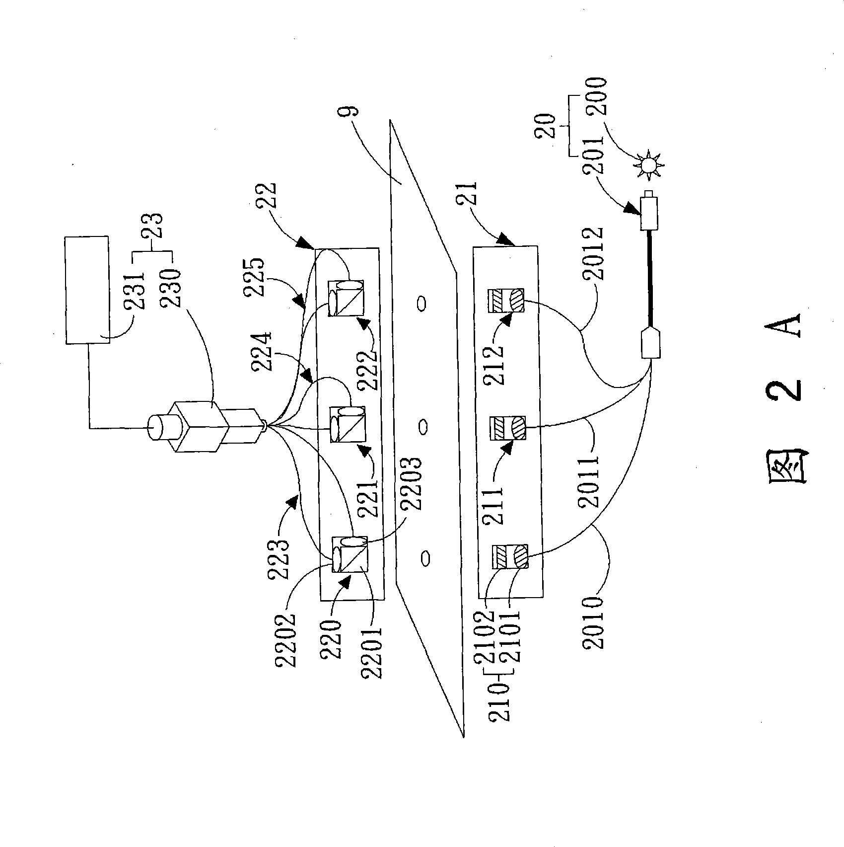
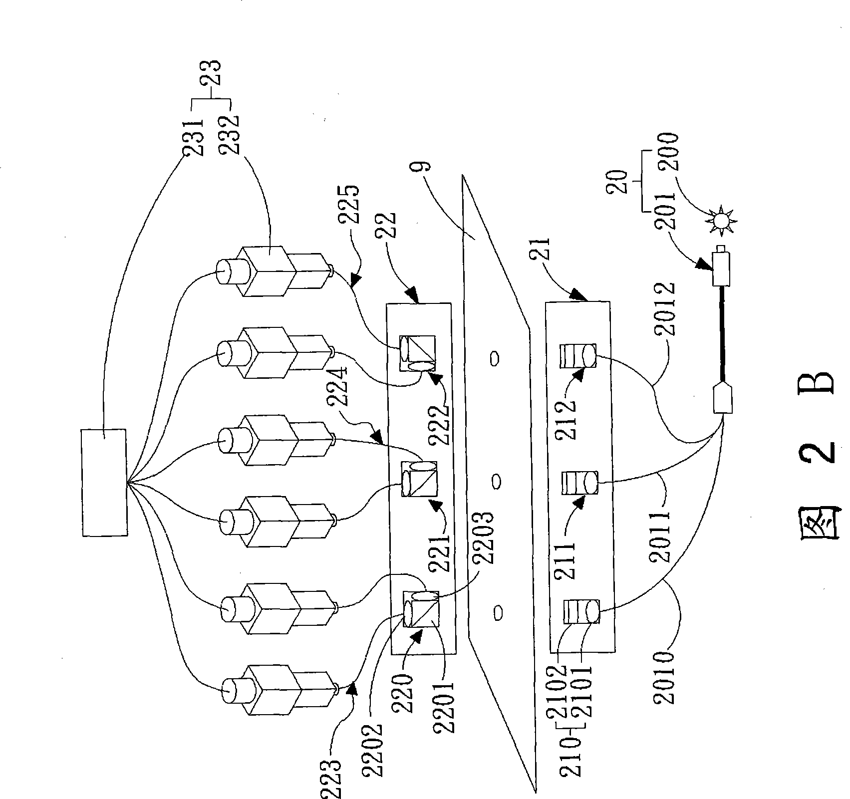
[0110] An example of the present invention provides a multi-channel spectral measurement device, which uses a multi-channel image spectrometer combined with an optical fiber array polarized beam control probe to simultaneously measure multiple sample points to be measured and flexibly change the measurement position, Suitable for sample measurement of different areas.

[0111] An example of the present invention provides a multi-channel spectrum measurement device. The light-receiving probe uses a polarization beam splitter to measure the phase difference without rotating the component, which is beneficial for fast real-time detection.

[0112] An example of the present invention provides a multi-channel spectral measurement device, which can greatly reduce the cost of the instrument when combined with a multi-channel spectrometer. In addition, a broadband white light source is used to measure the distribution of the phase difference corresponding to the wavelength, which is be...


PUM


Abstract

The invention discloses a multi-channel Optical Spectrum measurement device, which integrates a multi-channel imaging spectrograph with an optical fiber array type polarized beam steering probe to realize the simultaneous measurement of a plurality of sample spots to be tested. With respect to the design of a polarized beam absorption probe, a polarized beamsplitter is utilized to split received polarized beam into an incident polarized beam and a vertical polarized beam, and the two beams are absorbed by two groups of focusing lenses to the optical fiber array multi-channel imaging spectrograph respectively; thus, when the rotation of the absorption polarized beam probe is not required, a normalized strength spectrum signal of the vertical polarized beam and the incident polarized beam can be rapidly calculated and acquired according to energy loss calibrating parameters and measurement of the polarized components of a p wave and an S wave of the polarized light, and phase separation parameters can be obtained by mathematical manipulation.

Description

technical field [0001] The present invention relates to a spectral measurement and correction analysis method, in particular to a multi-channel spectral measurement device and its spectral intensity energy loss correction method, spectral intensity normalized measurement method and phase difference analysis method. Background technique [0002] The liquid crystal display industry is a key industry developed in the 2 trillion double star after the semiconductor industry. Its advantages of thinness, low energy consumption and no radiation have almost replaced the traditional image tube screen. Among the components used in liquid crystal panels, components with optical birefringence characteristics such as liquid crystal layer (Liquid Crystal Cell) and optical compensation film (compensation film), etc., the quality of their optical properties greatly affects the image quality of liquid crystal display. [0003] The development of liquid crystal display has gradually developed ...

Claims


Application Information

Patent Timeline
IPC IPC(8): G02F1/13G01B11/06
Inventor 刘志祥庄凯评林友崧
Owner IND TECH RES INST
Why Eureka
Try Eureka