Process and device for rewinding feed spools

A yarn and yarn guide technology is applied in the directions of transportation and packaging, transportation of filamentous materials, and thin material processing. It can solve problems such as reducing yarn quality, reduce yarn breakage, improve process conditions, and achieve high winding speed. Effect

Inactive Publication Date: 2009-05-20
邓肯多夫德国纺织纤维研究所
View PDF3 Cites 1 Cited by
  • Summary
  • Abstract
  • Description
  • Claims
  • Application Information

AI Technical Summary

Problems solved by technology

This leads to the practice that, in order to increase the throughput, the yarn quality has to be reduced due to the rewinding process.

Method used


Image

  • Process and device for rewinding feed spools
  • Process and device for rewinding feed spools
  • Process and device for rewinding feed spools

Examples


Embodiment Construction

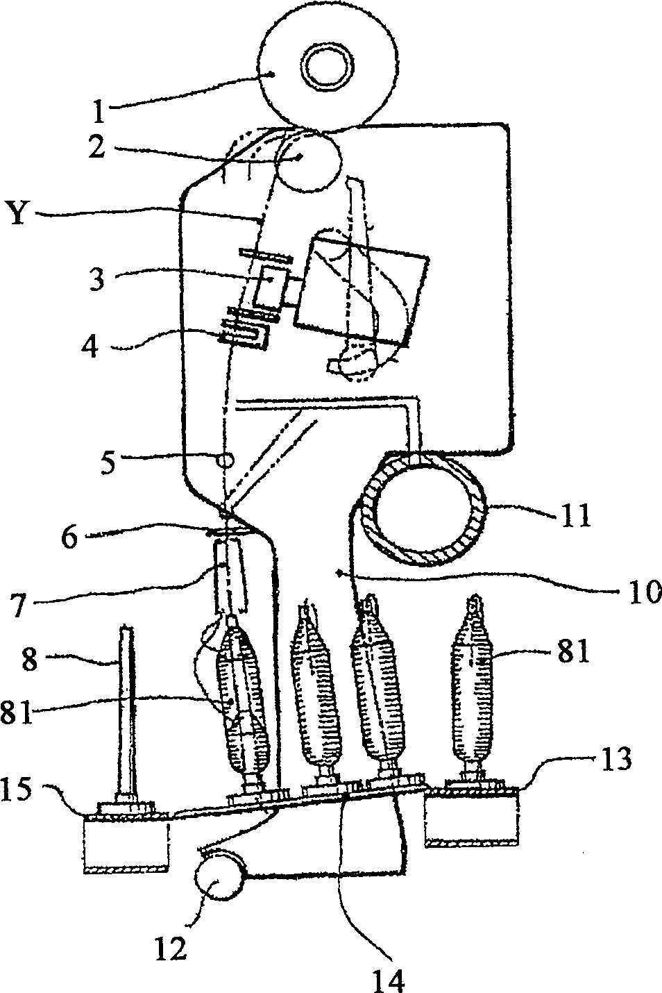
[0020] figure 1 A conventional design is shown in the winding state, with a winding spool 1 , which is generally configured as a conical or cylindrical crossing spool and is driven by a winding roller or grooved drum 2 . Here, the yarn Y is withdrawn from the weft tube or from the yarn supply shaft 81 via the top of the yarn tube 8 . Between the top of the bobbin 8 and the winding bobbin 1, a yarn guide 6, a tensioning device 5, a slub defect detector 4 and a splicing device 3 are generally arranged. Between the yarn Y take-off point at the weft tube 81 and the yarn guide 6 a yarn balloon is formed which, due to the centrifugal force of the yarn Y linked to the unwinding speed, causes a very high yarn tension and thus limits the unwinding speed. Therefore, if figure 1 As shown in , the balloon breaking device 7 is arranged above the weft tube 81 in front of the yarn guide 6 to prevent the formation of a larger balloon. The weft tubes 81 are conveyed by means of the supply ...


PUM

PropertyMeasurementUnit
Lengthaaaaaaaaaa
Heightaaaaaaaaaa
Heightaaaaaaaaaa

Abstract

A process and device are disclosed for rewinding thread feed spools produced on a ring spinning machine, the spools having a cone at their upper end that ends at the spool holder. The threads to be rewound are drawn overhead from the feed spools, joined and wound into a cross-wound bobbin. The usual gap between the top edge of the thread feed spool holder and the thread guide is considerably increased, so that the thread crosses a free section of more than 600 mm, and is not exposed to any further guidance in this section.

Description

technical field [0001] The invention relates to a method and a device for rewinding a yarn feeder spool, made for example on a ring spinning machine, which has at its upper end a cone tapering towards the bobbin and above which the yarn is drawn off the bobbins in which the rewound yarns of the respective feed spools are interconnected and wound onto cross bobbins, and the yarn sent from the feed spools passes through a yarn guide before entering the swinging position The yarn device is arranged at a distance from the yarn feeding shaft. Background technique [0002] Such yarn supply bobbins are produced, for example, on ring spinning machines and are often referred to as weft tubes. In order to obtain large yarn lengths, these bobbin yarns are rewound on conical or cylindrical cross-winding bobbins by automatic winding devices, removing yarn defects such as slubs and the like in the process. [0003] In order to achieve high rewinding speeds, a rewinding processing device...

Claims


Application Information

Patent Timeline
IPC IPC(8): B65H49/02
CPCB65H2701/31B65H49/02B65H59/02
Inventor 拉里莎·奥什克斯乌韦·海特曼
Owner 邓肯多夫德国纺织纤维研究所
Why Eureka
Try Eureka