
Input module for key encoder

A technology of input modules and encoders, applied to instruments, data processing input/output process, pulse technology, etc., can solve the problems of complex structure, huge circuit, high production cost, etc., and achieve compact and simple circuit structure, easy to organize mass production , the effect of low production cost

Inactive Publication Date: 2010-06-02
陈峰
View PDF3 Cites 1 Cited by
  • Summary
  • Abstract
  • Description
  • Claims
  • Application Information

AI Technical Summary

Problems solved by technology

In order to distinguish the key codes of each key, each column must have a set of column receivers with photoelectric conversion circuits directly corresponding to the key reflective surface. Taking a computer keyboard as an example, in the case of a total of 6 rows and 21 columns, the solution requires a total of The 21 column receivers (including 21 sets of photoelectric conversion circuits) correspond to the key reflective surfaces of the keys. This technical solution only needs to fix 21 sets of column receivers. The solution requires a large number of components, large circuits and complex structures, high production costs, difficult to take waterproof measures, and difficult to organize mass production. The production cost is several times that of traditional keyboards, which seriously affects the promotion and use of photoelectric keyboards.

Method used


Image

  • Input module for key encoder
  • Input module for key encoder
  • Input module for key encoder

Examples


Embodiment 1

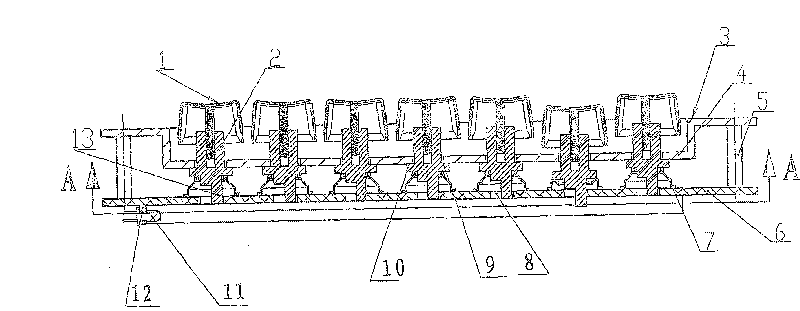
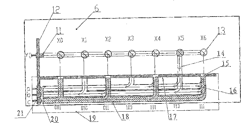
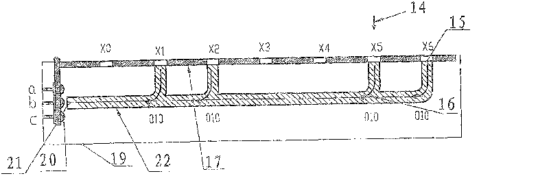
[0039] see figure 1 , figure 2, the present invention is made up of horizontally arranged keys, signal transmitter 11, elastic body 7, housing, extension 13, optical encoder 19, photoelectric input circuit controller (not shown in the figure) and the like.

[0040] see figure 1 , figure 2 The panel 3 is in the shape of a flat plate with a concave middle part, and there are panel through holes 9 evenly distributed horizontally on the concave bottom surface 4 with a square middle part. The bottom plate 6 is in the shape of a flat plate, and the panel 3 and the bottom plate 6 are connected by four columns 5 to form a hollow housing parallel to each other. A signal transmitter 11 and a receiver are respectively installed on the lower surface near the left part of the bottom plate 6. The left vertical plate 12 of 20.

[0041] see figure 1 Keycap 1 is fixedly connected with the top of key guide body 2 to form a button, the bottom surface of elastic body 7 is connected with...

Embodiment 2

[0059] see Figure 13 The signal transmitter 11 corresponds to the front end of the tree-like light-splitting main light guide 35, and one end of several tree-like light-splitting sub-light guides 36 meets the tree-like light-splitting main light guide 35, and the other end corresponds to the front end of the tree-like incident sub-light guide 38, and the tree-like incident The end of the sub-light guide 38 intersects with the tree-like incident main light guide 37, and the end of the tree-like incident main light guide 37 corresponds to the light input end 15 of the beam splitter 18; Between the two ends of the tree-shaped photon light guide 36 and the incident sub-light guide 38 .

[0060] see Figure 13 There is a tree-shaped light-splitting light guide composed of a tree-shaped light-splitting main light guide 35 and a tree-shaped photon light guide 36 corresponding to one end of which is a tree-like structure, and several tree-shaped light-splitting light guides 36 and t...

Embodiment 3

[0067] see Figure 14 The downward extension 13 of the shoulder 10 on the key guide 2 of the button is fixedly connected to one end of the tree-shaped photon light guide 36, and the other end of the tree-shaped photon light guide 36 meets the tree-shaped main light guide 35. When the key is not pressed When pressed down, the tree-shaped incident sub-light guide 38 does not correspond to the end face of the tree-shaped photo-splitting sub-light guide 36 .

[0068] The key optical switch is arranged on the optical path that can make the optical input end 15 of the optical splitter 18 communicate with the signal transmitter 11 optical path. The tree-like sub-photon light guide 36 , the tree-like incident sub-light guide 38 and the extension part 13 fixedly connected to the free end of the tree-like photon-light guide 36 can be linked with the keycap 1 .

[0069] see Figure 15 There is a tree-shaped light-splitting light guide composed of a tree-shaped light-splitting main ligh...


PUM


Abstract

A key encoder input module for keyboard which transmitting signal with light, and the cost of manufacture is low. The key encoder input module includes circuit controller, keycap which setup on casingand connected with elastomer, multiple signal emitters and receivers. The key encoder input module also includes a light splitter, a key optical switch is set under the keycap, signal sent by the signal emitter corresponds to the light input port of the light splitters through key light switch, a light encoder is formed between the light splitters and receivers by connecting them with the light path of the light splitters. When a keycap is pressed, signal emitter conducts with the light path of receiver and forms light splitting path after passing the key light switch and light splitter whichperforming permutation and combination to light path, and light encoder outputs a set of key code signal corresponding to the key position of the keycaps to the input circuit controller. The key encoder input module has the advantages of that the configuration is simple, the cost is basically equal to the traditional keyboard, and the number of photocells used is small. For example, the computerkeyboard usually needs a phototranslating circuit with 5 sets of receivers, and produces 2<5>key codes, namely 32 sets of key codes. And the receiver does not need to directly correspond to light switch of keys in rows. The phototranslating circuit including receivers may be set on the same printed plate with emitters and main control chip. The key encoder input module has the advantages that theconfiguration of circuit is tight and simple, the cost of production is low, and it is easy to organize batch production. It is convenient to take steps to pressurize a bit of printed plate, so that the keyboard is wholly rainproof, even may be used in water.

Description

Technical field [0001] The invention relates to a signal transmission module for a keyboard, in particular to an input module using light for signal transmission. Background technique [0002] Existing key encoder input modules such as Figure 11 As shown, the key reflective photoelectric switch circuit is used. When the key is pressed, the key reflective surface reflects the different frequency signals sent by the row signal transmitter to the column receiver, and then processed by the input circuit controller to obtain a key of each position. Corresponding key code signal. In order to distinguish the key codes of each key, each column must have a set of column receivers with photoelectric conversion circuits directly corresponding to the key reflective surface. Taking a computer keyboard as an example, in the case of a total of 6 rows and 21 columns, the solution requires a total of The 21 column receivers (including 21 sets of photoelectric conversion circuits) correspon...

Claims


Application Information

Patent Timeline
IPC IPC(8): G06F3/042
CPCH03K17/969
Inventor 陈峰
Owner 陈峰
Learn More