Check patentability & draft patents in minutes with Patsnap Eureka AI!

Swivel arm actuator for multiple directions of movement

A technology of motion direction and actuator, which is applied in the direction of optical recording/reproduction, instrument, head configuration/installation, etc., and can solve the problem of swing arm actuator not being resistant to impact, etc.

Inactive Publication Date: 2009-05-20
THOMSON LICENSING SA
View PDF4 Cites 0 Cited by
  • Summary
  • Abstract
  • Description
  • Claims
  • Application Information

AI Technical Summary

Problems solved by technology

This swing arm actuator has the disadvantage of not being impact resistant

Method used


Image

  • Swivel arm actuator for multiple directions of movement
  • Swivel arm actuator for multiple directions of movement
  • Swivel arm actuator for multiple directions of movement

Examples


Embodiment Construction

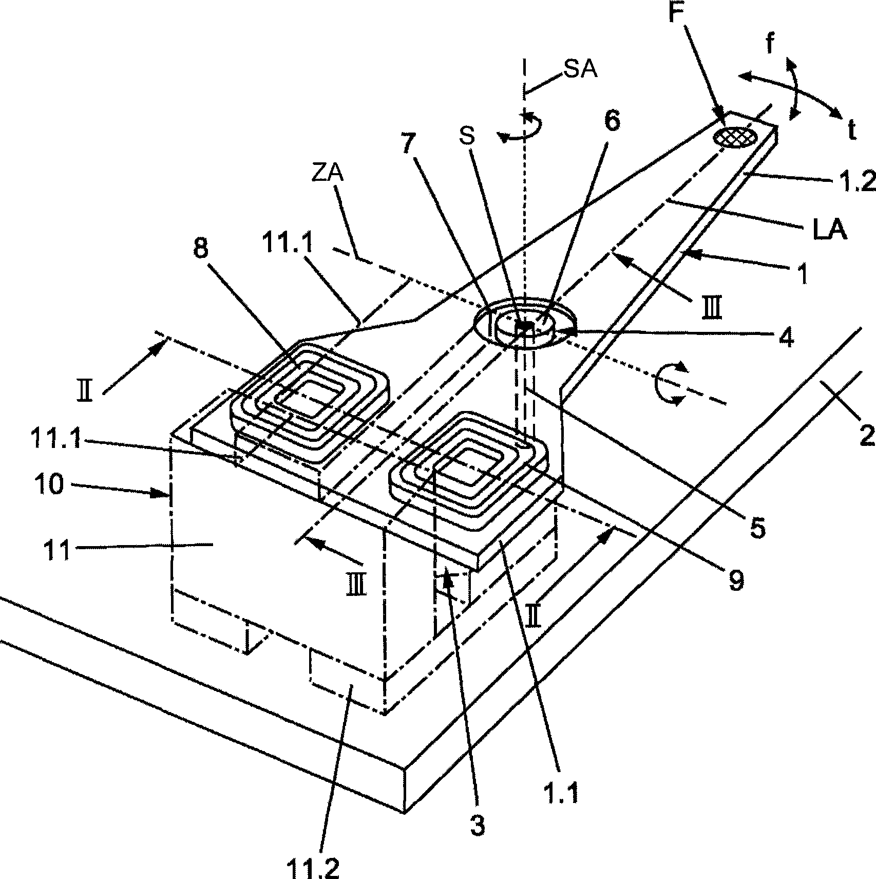
[0018] figure 1 The swing arm actuator shown for an optical scanning device (not shown) has a bending-resistant and torsion-proof swing arm 1, which is mounted universally in its center of gravity S in the form of a double-armed lever. On the support 2; the swing arm actuator also has a magnetic driver 3 effectively connected with the swing arm 1. The slewing bearing 4 is designed to keep a certain distance from the support 2 on a hinge pivot 5 fixedly arranged on the support 2 and erected perpendicular to the support 2, and includes a rotatable support on the hinge pivot 5 The upper bearing race 6 and two pivot pins 7 arranged on the bearing race 6 transversely to the longitudinal axis LA of the swing arm 1 , on which the swing arm 1 is held in a rotatable manner. The rotatability occurs on the one hand about the axis SA of the hinge pivot 5 in a plane parallel to the support 2 and on the other hand about an axis ZA formed by the pivot pin 7 perpendicular to this plane.

[...


PUM


Abstract

The invention relates to a swivel arm actuator that moves in multiple directions with a swing arm designed as a supported two-armed lever that is supported on a support and can swivel and that is equipped with a moving part on one of its levers or is actively connected to such and that is equipped on the other lever arm with a magnetic drive for an initial swivel motion around an axis that runs vertical to the swivel arm and to which a magnetic drive is assigned for movements vertical to this swivel motion. It teaches building a swivel arm of this type with little cost. For this purpose, both magnet drives are fixed together in the magnetic drive (3) which is situated on the lever arms (1.1) used on component (F) and this single magnetic drive (3) is designed to generate an inhomogeneous magnetic field with which both the initial swivel motion of part (F) and the motion of part (F) vertical to it is possible.

Description

technical field [0001] The invention relates to a swing arm actuator for multiple directions of motion, in particular to a swing arm actuator with an optical head for an optical scanning device, the optical scanning device In a device used to record and / or play back information. Background technique [0002] An actuator in an optical scanning device with an optical head with a focusing lens, which is used to emit light (laser beam) to an optical plate designed as an information carrier and to receive light from the optical plate reflected light. Different types of arrangements and types of movement of such actuators within scanning devices have been disclosed. In the first type, the optical head is set on the slider, which moves back and forth above the optical plate in a straight line in a plane parallel to the optical plate and can focus, while in the second type, the optical head Arranged at the free end of the swing arm designed as a double-armed lever, the swing arm ...

Claims


Application Information

Patent Timeline
IPC IPC(8): G11B7/085G11B7/09
CPCG11B7/0935G11B7/08576G11B7/0933
Inventor 弗兰克·普齐戈达
Owner THOMSON LICENSING SA
Features
  • R&D
  • Intellectual Property
  • Life Sciences
  • Materials
  • Tech Scout
  • Unparalleled Data Quality
  • Higher Quality Content
  • 60% Fewer Hallucinations
Learn More