
Bus connector

A busbar connector, grounding wire technology, applied in the direction of connection, clamping/spring connection, protective grounding/shielding device of connecting parts, etc. To reliable guarantee, the size of the cabinet becomes larger, etc., to achieve the effect of miniaturization of cabinet design, compact structure and small volume

Inactive Publication Date: 2009-05-27
GCA CO LTD
View PDF0 Cites 10 Cited by
  • Summary
  • Abstract
  • Description
  • Claims
  • Application Information

AI Technical Summary

Problems solved by technology

Existing busbar connectors: ①The contacts are composed of sheet contacts. Under the same installation and use conditions, the contacts of this structure have low current capacity and the rated current can only reach 630A
Due to the continuous rapid development of the national economy and the continuous increase in power consumption, users put forward higher requirements for the performance indicators of switchgear, and the low rated current limits the development and application of gas-insulated metal-enclosed switchgear
② There is no supporting aluminum tube in the inner cavity of the rubber sleeve
When the switchgear is spliced, the insulation coordination between the busbar connector and the busbar insulator is the key to ensure its electrical performance, but without the busbar connector supporting the aluminum tube, the interface pressure of the insulation coordination will not be reliably guaranteed
③The product structure is large in size
The structural size of the busbar connector directly affects the cabinet size and manufacturing cost of the switchgear. A large structural size will inevitably increase the cabinet size of the switchgear and increase the product cost

Method used


Image

  • Bus connector
  • Bus connector
  • Bus connector

Examples


Embodiment Construction

[0009] The present invention will be further described below in conjunction with a preferred embodiment and accompanying drawings.

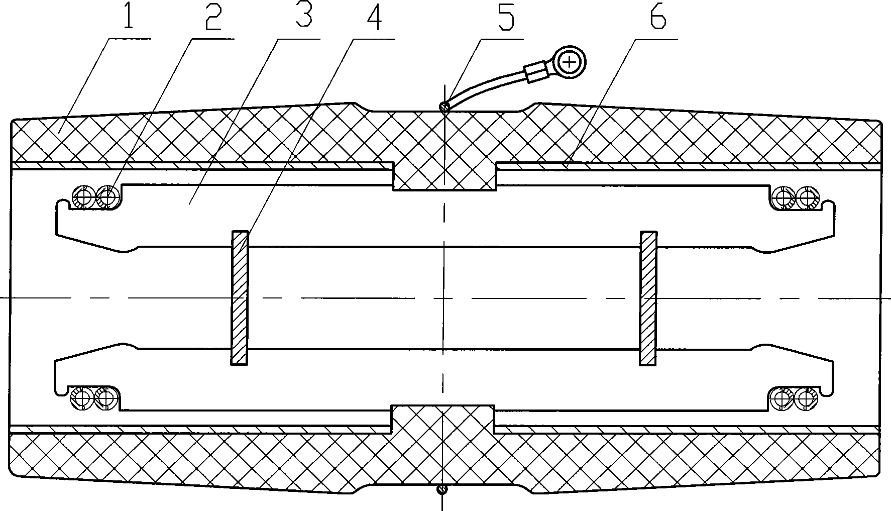
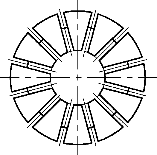
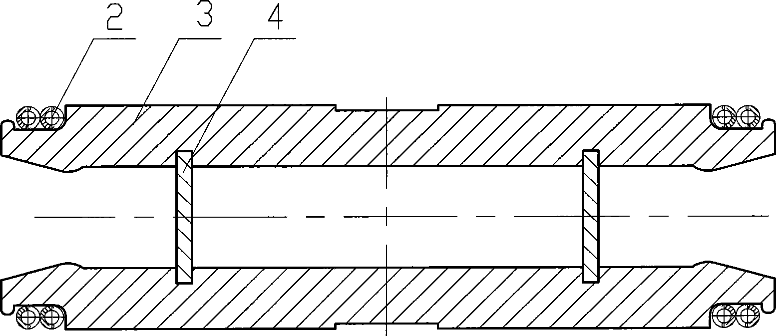
[0010] as attached figure 1 , attached Figure 2A , 2B As shown, this embodiment is mainly composed of a rubber sleeve 1, a spring 2, a fan-shaped contact piece 3, a grid piece 4, a ground wire group 5, and an aluminum tube 6. The fan-shaped contact piece 3 is installed in the slot of the grid piece 4, and then They are fixed together by a spring 2 to form a fan-shaped contact 7 . Install aluminum tubes 6 at both ends of the inner cavity of the rubber sheath 1, then insert sector contacts 7, and then install a ground wire group 5 in the middle of its outer surface to form a busbar connector. After the above-mentioned structure is adopted in the present invention, the busbar connector has a strong flow capacity, can meet the requirements of a switchgear with a rated current of 1250A when combining cabinets, and has a design use margin of 1.2 ti...


PUM


Abstract

The invention relates to a busbar connector used in a gas-insulated metal-enclosed switchgear of 24 kV or less than 24 kV. The busbar connector mainly comprises a rubber sleeve, a spring, a sectorial wafer, a grid plate, a ground wire group and aluminum tubes, wherein the sectorial wafer is arranged inside a clamping groove of the grid plate, and the sectorial wafer and the grid plate are fixed with each other by the spring to form a sectorial contact; and the aluminum tubes are arranged on both ends of an inner cavity of the rubber sleeve, the sectorial contact is inserted into the rubber sleeve, and the ground wire group is arranged in the middle of the outer surface of the rubber sleeve, so that the busbar connector is formed. The gas-insulated metal-enclosed switchgear of 24 kV or less than 24 kV using the busbar connector to assemble machine cabinets has good discharge current capability, a compact structure, reliable quality and superior insulating property, and improves the stability and the safety of equipment operation.

Description

Technical field: [0001] The invention relates to the technical field of insulators used in gas-insulated metal-enclosed switchgear of 24kV and below, in particular to a busbar connector. Background technique: [0002] In the process of design, installation and use of 24kV and below gas-insulated metal-enclosed switchgear, the splicing mode between switchgear, the design and selection of insulating parts and the control of installation quality have always been considered by product designers and engineering installers. This is because the technical index of the insulating part is the bottleneck of the overall equipment performance index. Only by improving the technical level of the insulating part can the technical level of the overall equipment be improved, and the safety and stability of the overall equipment operation can be improved. Existing busbar connectors: ①The contacts are composed of sheet contacts. Under the same installation and use conditions, the contacts of th...

Claims


Application Information

Patent Timeline
Patent Type & Authority Applications(China)
IPC IPC(8): H01R25/16H01R4/48H01R13/648
CPCH02B13/005
Inventor 陈朝晖杨家坤刘上金黄铭昌
Owner GCA CO LTD
Learn More