Ball bearing cage

A technology for ball bearings and races, applied in the direction of ball bearings, bearing elements, shafts and bearings, etc., can solve problems such as excessive wear of races, degradation of bearing lubrication, etc., to reduce wear of races and balls, reduce deformation, and lighten The effect of the axial part

Active Publication Date: 2009-05-27
AB SKF
View PDF1 Cites 6 Cited by
  • Summary
  • Abstract
  • Description
  • Claims
  • Application Information

AI Technical Summary

Problems solved by technology

Deformations such as this have a detrimental effect on the correct operation of rolling bearings, since the edges of the dimples compress the balls, increase the frictional moment and scrape the lubricant, which quickly leads to accelerated degradation of the bearing lubrication
There is also the risk that the ends of the claws will contact the bore of the bearing outer ring, prone to excessive race wear

Method used


Image

  • Ball bearing cage
  • Ball bearing cage
  • Ball bearing cage

Examples


Embodiment Construction

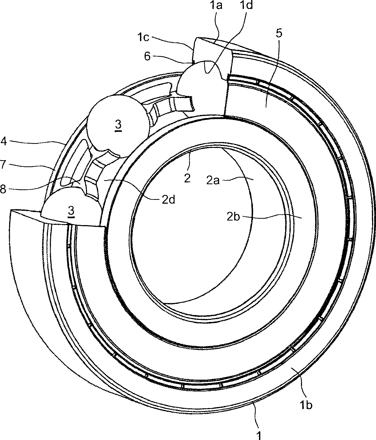
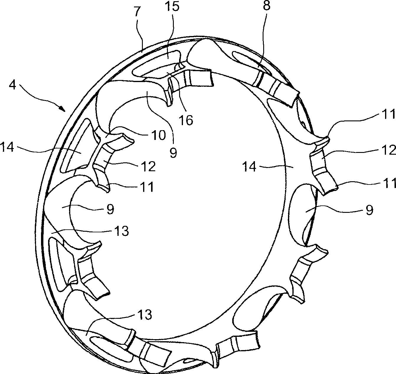
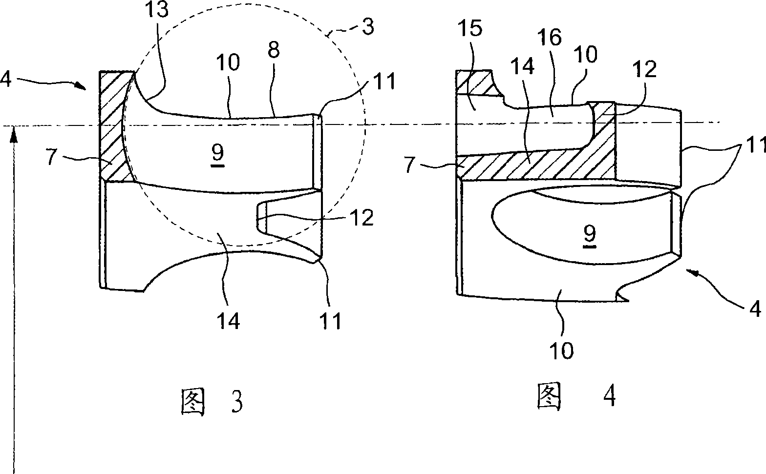
[0034] from figure 1 As can be seen in , the rolling bearing assembly includes an outer ring 1; an inner ring 2; a row of rolling elements 3, in this case balls; a race 4 for maintaining the circumferential spacing of the rolling elements 3; and sealing plates 5 and 6.

[0035] The outer ring 1 and the inner ring 2 are deep grooved, for example formed by machining a part of a pipe. The outer ring 1 comprises a cylindrical axially outer surface 1 a ; opposite radial front surfaces 1 b and 1 c ; and a bore forming a raceway 1 d for the rolling elements 3 . The inner ring 2 comprises a cylindrical bore 2 a ; two opposite radial front surfaces 2 b and 2 c ; and an outer surface forming a track 2 d for the rolling elements 3 . The outer ring 1 is equipped with two symmetrical sealing grooves into which sealing plates 5 and 6 fit respectively from the same side as the radial surface 1 b and the same side as the radial surface 1 c. The sealing plates 5 and 6 form narrow passages, a...


PUM


Abstract

Ball bearing cage (4) consisting of a bead ring (7) and a substantially axial portion (8) fitted with claws (11) that define alveolus (9) for balls and joining on the bead (7), the substantially axial portion (8) stretching axially on one portion of the alveolus (9). The substantially axial portion (8) presents an external diameter inferior to the external diameter of the bead (7), the external diameter of the substantially axial portion being comprised between the primitive diameter of the cage reduced to half of the radial thickness of the diameter of the bead and the primitive diameter increased to half of the radial thickness of the bead.

Description

technical field [0001] This invention relates to the field of rolling bearing races, in particular composite races for use in deep groove ball bearings to provide proper circumferential spacing between balls. The invention also relates to a raceway of a rolling bearing in which the rings are made of sheet metal. Background technique [0002] These types of races generally have an annular shape with spherical pockets in which the balls are partially housed. The balls are retained in the pockets by means of claws arranged in pairs on opposite sides of the raceway root. The diameter of the spherical dimple is slightly larger than that of the ball in order to maintain a specific functional clearance between the ball and the dimple. Reference may be made to the abstract of document JP2002 / 147463 (NSK), wherein the radial thickness of the claws is gradually thinned from the root. [0003] When rolling bearings run at high speeds, centrifugal forces subject the races to stresses...

Claims


Application Information

Patent Timeline
Patent Type & Authority Applications(China)
IPC IPC(8): F16C33/41
CPCF16C33/6614F16C33/418F16C33/416F16C19/06F16C33/38F16C33/41
Inventor 阿梅尔·L·多耶弗兰克·贝伦斯蒂里·阿丹尼古拉斯·贝利厄尔亚历山大·曼西厄
Owner AB SKF
Why Eureka
Try Eureka