Position detection equipment and method for detecting jet hole of coater and light spot of laser displacement sensor

A technology of laser displacement and detection equipment, which is applied in the direction of surface coating liquid devices, measuring devices, spraying devices, etc., can solve the problems of long time consumption and low detection accuracy, and achieve improved accuracy and detection time, The effect of improving accuracy

Active Publication Date: 2009-06-03
TOP ENG CO LTD
View PDF0 Cites 14 Cited by
  • Summary
  • Abstract
  • Description
  • Claims
  • Application Information

AI Technical Summary

Problems solved by technology

[0013] However, in the known position detection method, since the worker visually checks the position of the nozzle and the position of the laser displacement sensor provided in each head unit, in the case where the glue applicator is provided with a plurality of head units, there will be many The problem is that it takes a long time to detect the position of the nozzle and the laser displacement sensor, and the detection accuracy is low

Method used


Image

  • Position detection equipment and method for detecting jet hole of coater and light spot of laser displacement sensor
  • Position detection equipment and method for detecting jet hole of coater and light spot of laser displacement sensor
  • Position detection equipment and method for detecting jet hole of coater and light spot of laser displacement sensor

Examples


no. 1 example

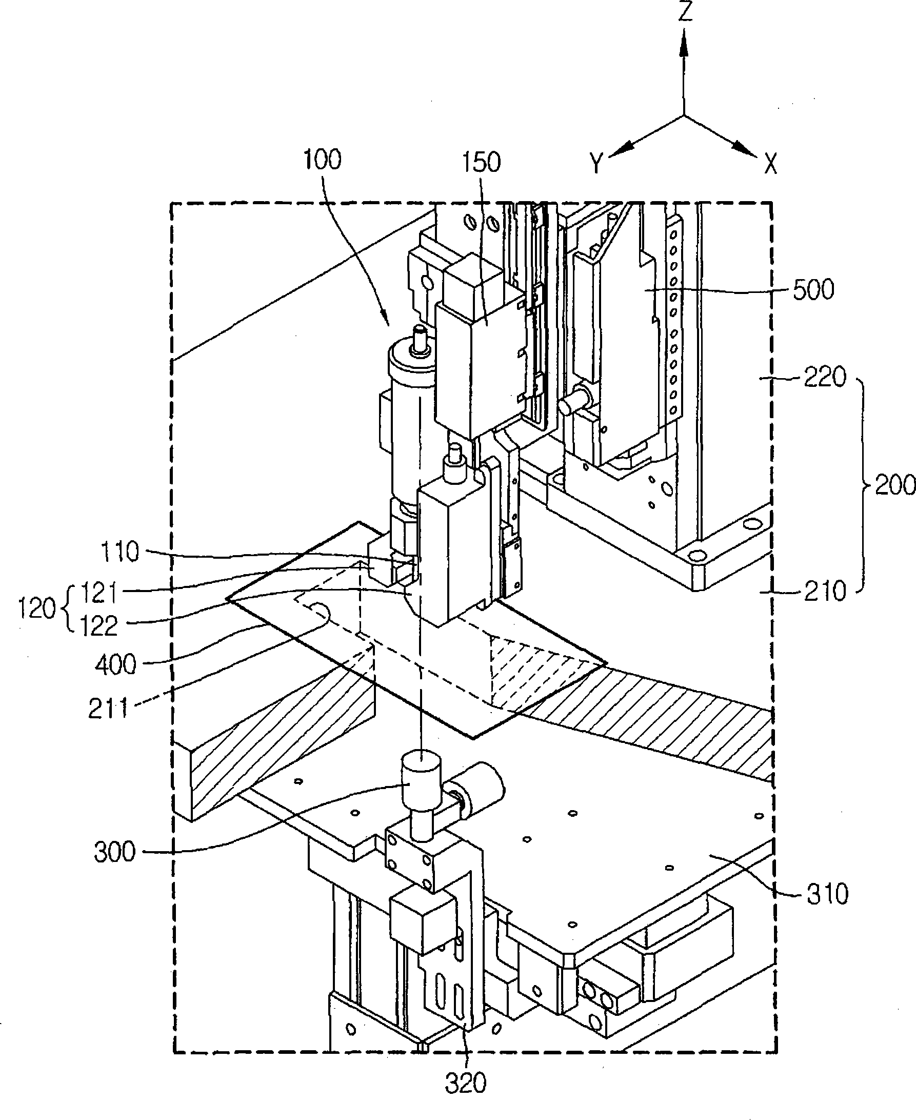
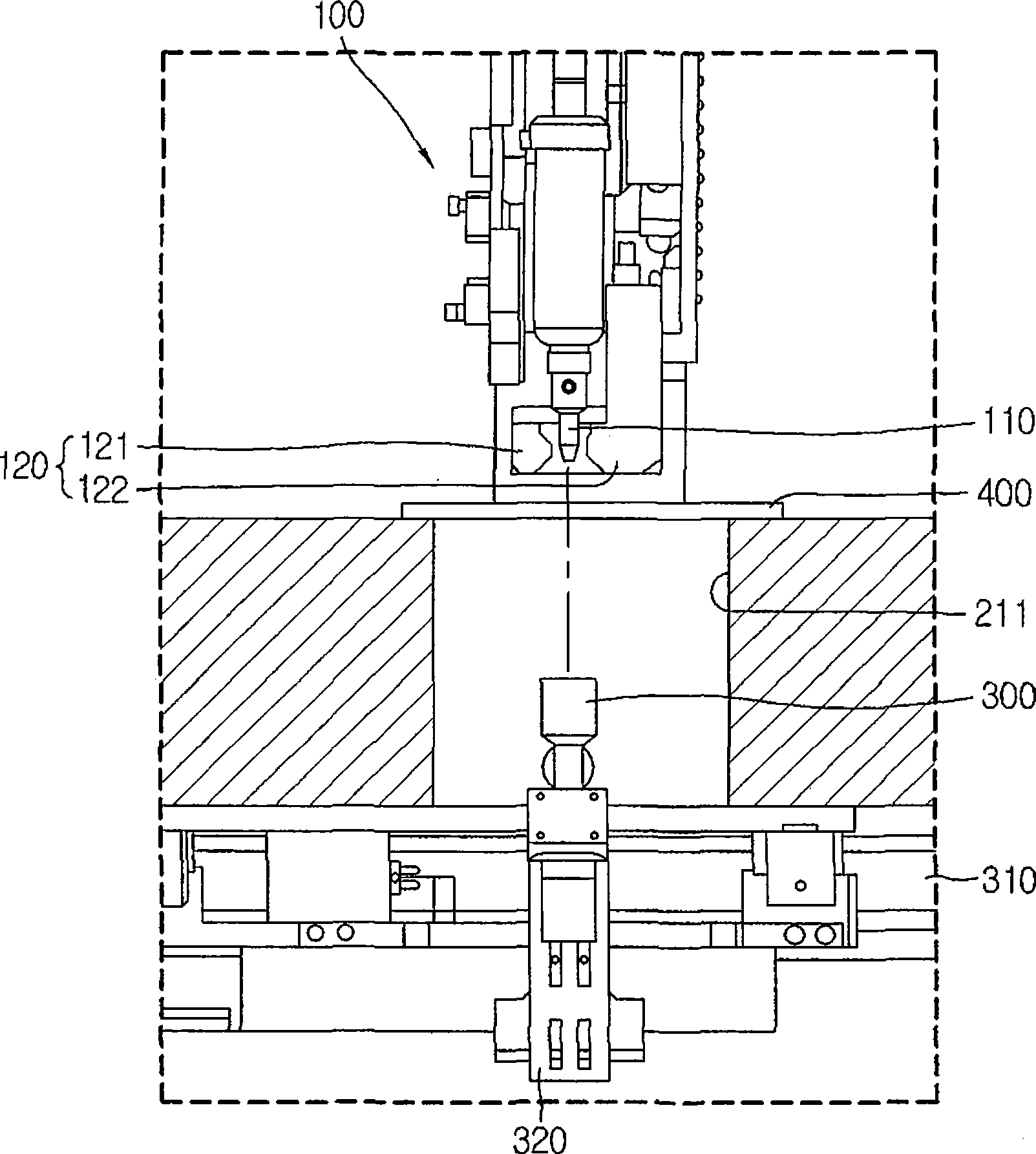
[0036] refer to Figures 1 to 6 , the position detecting device and the position detecting method which detect the positions of the discharge hole of the nozzle of the glue applicator and the light spot of the laser displacement sensor according to the first embodiment will be described.

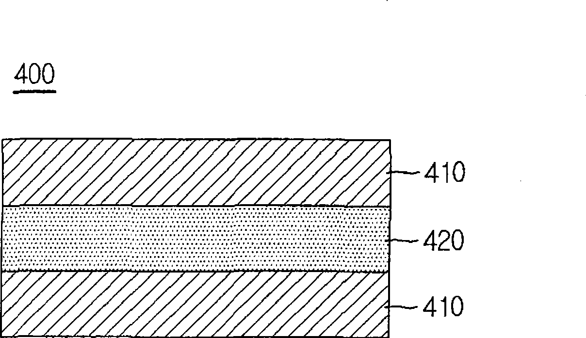
[0037] figure 1 is a perspective view showing a position detection device for detecting the positions of a discharge hole of a nozzle of a glue applicator and a laser displacement sensor according to a first embodiment of the present invention, figure 2 is shown figure 1 Front view of the position detection device shown, image 3 is shown figure 1 A cross-sectional view of the variable transmittance member of the position detection device shown, Figure 4 is shown figure 1 Block diagram of the position detection device shown, Figure 5 is a flowchart showing a position detection method using figure 1 The position detection device is shown to detect the position of the discharge hole ...

no. 2 example

[0059] In the following, reference will be made to Figure 7 A position detection device and a position detection method for detecting the positions of a discharge hole of a nozzle of a glue applicator and a light spot of a laser displacement sensor according to a second embodiment of the present invention are described. In the first embodiment and the second embodiment, the same elements and process steps are denoted by the same reference numerals, and descriptions thereof may be omitted.

[0060] According to the second embodiment, the position detection method detects the positions of the discharge hole 115 of the nozzle 110 and the light spot 125 of the laser displacement sensor 120 using the characteristics of the PDLC element 420 changed from the first state to the second state. In the first state, even without supplying power to the PDLC element 420, if a predetermined pressure is applied to the PDLC element 420, the orientation of the liquid crystal in the PDLC element...


PUM


Abstract

The present invention discloses position detection equipment and a position detection method for a coater, capable of detecting the position of a light spot of a laser displacement sensor of the coater and a discharge hole of a nozzle. The position detection equipment includes a head support member for supporting a head unit equipped with a nozzle and a laser displacement sensor, a camera locating facing the nozzle and the laser displacement sensor, and a transmittivity variable member arranged among the nozzle, the laser displacement sensor and the camera,transferring from a first state to a second state or inversely. Under the first state, a laser beam is capable of being transmitted through the transmittivity variable member and projecting the torque of the nozzle; under the second state, the laser beam is reflected and imaged on the transmittivity variable member.

Description

technical field [0001] The invention relates to a position detection device and method, which are used to detect the position of the spray hole of a glue applicator and the light spot of a laser displacement sensor. Background technique [0002] A flat panel display (FPD) generally refers to an image display device that is thinner and lighter than a television or monitor with a cathode ray tube (CRT). As the FPD, liquid crystal displays (LCDs), plasma displays (PDPs), field emission displays (FED), organic light emitting diodes (OLEDs) have been developed and utilized. [0003] Among these displays, LCD is a display device configured to display images by adjusting the optical transmittance of liquid crystal elements by individually supplying data signals to liquid crystal elements arranged in a matrix based on information about images to realise. LCDs have become widely used due to their advantages such as being thinner with a lightweight body, low power consumption, and l...

Claims


Application Information

Patent Timeline
Patent Type & Authority Applications(China)
IPC IPC(8): B05B13/04G01B11/00G02F1/1339G02F1/1333
CPCB05C5/02B05C19/04G02F1/13
Inventor 朴学喆金熙根金正煜
Owner TOP ENG CO LTD
Why Eureka
Try Eureka