Method for installing and dismantling device for connecting main shaft of large-scale mine elevator with motor rotor

A technology of mine hoist and motor rotor, which is applied to lifting equipment, transportation and packaging in mines, can solve problems such as difficulty and inability to guarantee, and achieve the effect of simple and easy operation steps.

Active Publication Date: 2009-06-03
CITIC HEAVY INDUSTRIES CO LTD +1
View PDF4 Cites 4 Cited by
  • Summary
  • Abstract
  • Description
  • Claims
  • Application Information

AI Technical Summary

Problems solved by technology

The amount of interference determines the size of the torque transmitted by the cone surface, and the motor rotor is assembled at the user's site. Under the condition of limited assembly conditions on site, it cannot be guaranteed ...

Method used


Image

  • Method for installing and dismantling device for connecting main shaft of large-scale mine elevator with motor rotor
  • Method for installing and dismantling device for connecting main shaft of large-scale mine elevator with motor rotor
  • Method for installing and dismantling device for connecting main shaft of large-scale mine elevator with motor rotor

Examples


Embodiment 1

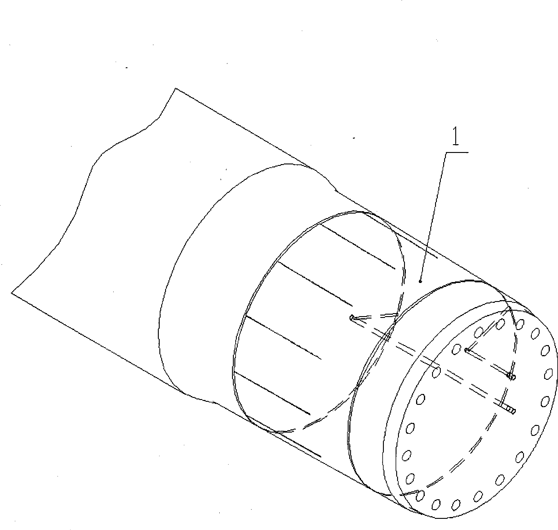
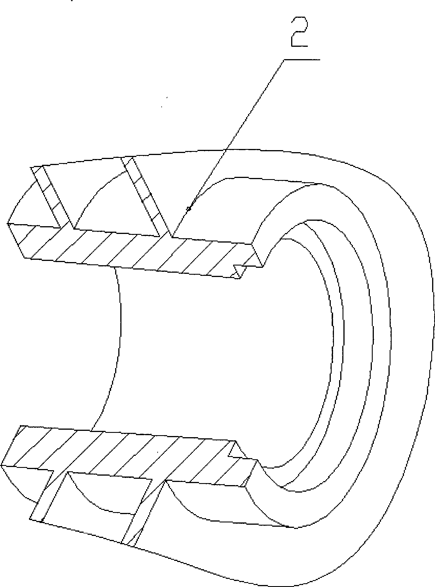
[0047] a. Clean the tapered hole of the motor rotor hub (2) and the tapered surface of the hoist main shaft (1), and there must be no oil, any other impurity particles and metal burrs.

[0048] b. Lift the motor rotor (2) with a crane, and place it on the shaft end of the main shaft (1).

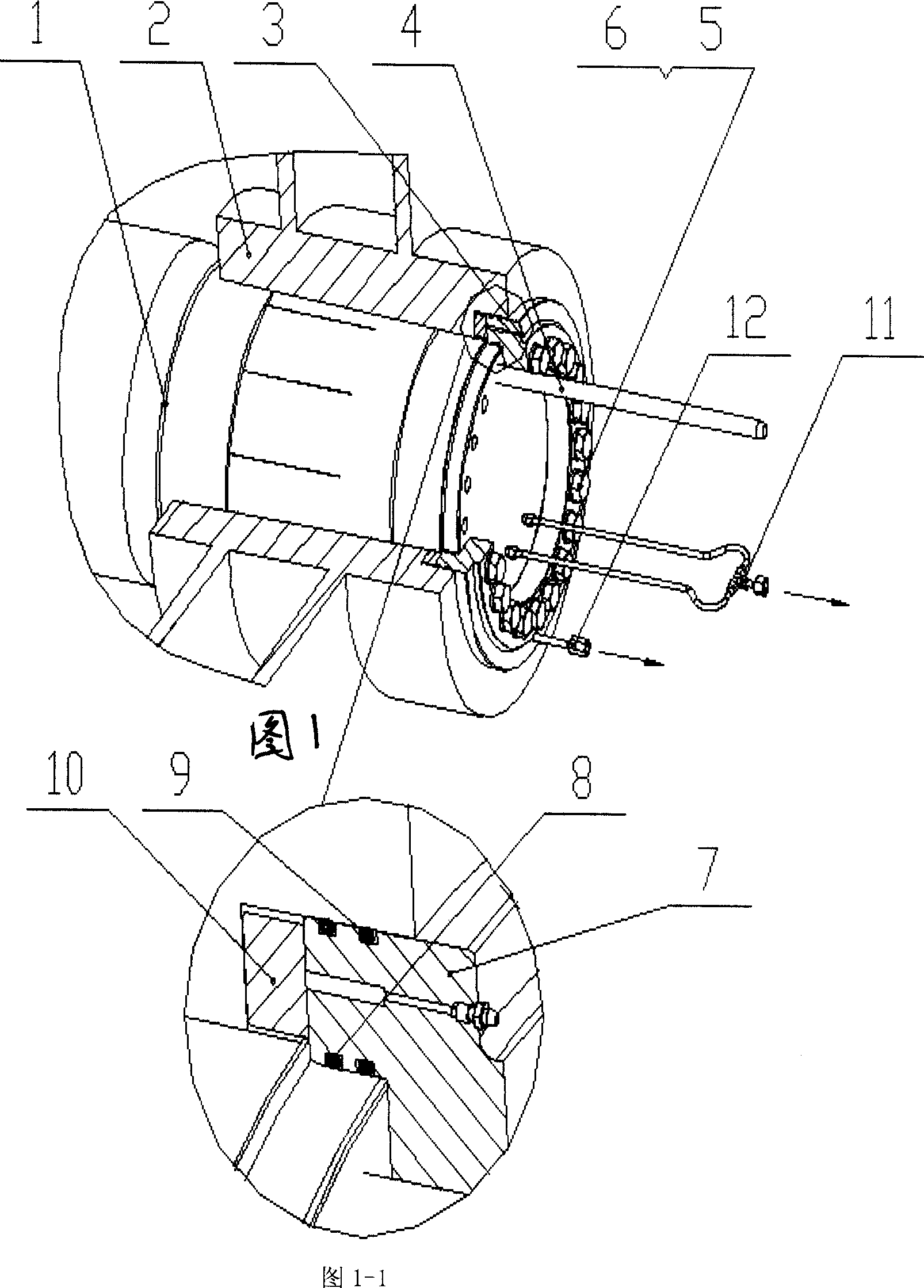
[0049] c. Put sealing ring 1 (8) and sealing ring 2 (9) on the hydraulic cover (7).

[0050] d. Screw the bleed screw (3) into the bleed hole on the hydraulic cover.

[0051] e. Use the installation rod (4) to install the hydraulic cover to the shaft end. It should be noted that the air release screw (3) must be placed at the upper position.

[0052] f. Install the bolts (5) and washers (6), and tighten the bolts.

[0053] g. Connect the oil pump, if attached Figure 5 shown.

[0054] Use the adapter 1 (11) to connect the oil hole on the shaft head with the oil pump 1 (13), so that the pressure oil goes along the axial oil path of the main shaft, and then reaches the mating surface of the...

Embodiment 2

[0056] h. Prepare to charge oil to the two oil pumps.

[0057] Oil pump 2 (14) gives the rotor axial thrust, and oil pump 1 (13) gives the rotor radial expansion force and forms an oil film between the contact surface of the rotor and the main shaft.

[0058] i. Make the hoisting rope for hoisting the rotor stressed, and the horizontal force makes the rotor as close as possible to the main shaft, and then use the oil pump 2 (14) to fill the cavity formed by the motor rotor and the hydraulic cover on the main shaft, and the air is fed by the air release screw (3) discharge.

Embodiment 3

[0060] Air release method: use oil pump 2 (14) to charge oil, the amount of oil is to fill the cavity formed by the motor rotor and hydraulic cover until oil overflows from the air release screw, loosen the air release screw, and the mixture of air and oil overflows , until there are no bubbles in the overflow, and it is all oil, tighten the air release screw.

[0061] j. Use the oil pump 2 (14) to give the oil pressure 0.5-3MPa, so that the rotor hub is in close contact with the main shaft, then mark the initial position of the rotor in the axial direction, and mark the end position that needs to be advanced according to the given advancing distance , while measuring the axial propulsion distance of the rotor with a dial gauge or a depth gauge. The axial propulsion distance of the rotor is determined by the taper of the main shaft cone and the interference. For example, if the taper is 1:30 and the calculated interference is 0.6mm, the propulsion distance is 30×0.6mm=18mm.


PUM


Abstract

A method for installing and dismantling a device for connecting the main shaft of a large-scale mine elevator with a motor rotor is characterized in that the device comprises an elevator main shaft (1), a motor rotor hub (2), an air bleed screw (3), a mounting rod (4), a bolt (5), a gasket (6), a hydraulic cover (7), a seal ring 1 (8), a seal ring 2 (9), a sleeve (10), a connecting pipe 1 (11), a connecting pipe 2 (12), an oil pump 1 (13) and an oil pump 2 (14). The invention solves the problems of accurate assembly of the motor rotor on the elevator main shaft and field dismantling of the motor rotor when conditions for field installation and assembly are limited. Tools for implementing the method are easy to process. The method comprises operation steps which are simple and easy to be carried out, so that installation workers, even totally ignorant of how to install a motor rotor, can still smoothly install and dismantle the motor rotor by following the requirements of instructions. Particularly, the invention is suitable for field use by users.

Description

technical field [0001] The invention relates to a method for assembling and disassembling a connecting device of a large mine hoist, in particular to a method for installing and disassembling a connecting device for a main shaft of a large mine hoist and a motor rotor. Background technique [0002] At present, the mechanical part of the traditional mine hoist is composed of three major parts: the main shaft device, the reducer and the motor. The hoist of the direct-coupled structure cancels the reducer and coupling of the intermediate transmission and the lubrication system of the reducer. The motor and the hoist are directly connected through the taper hole, and the rotor is suspended on the main shaft of the hoist through interference, and the hydraulic assembly is adopted. together. The amount of interference determines the size of the torque transmitted by the cone surface, and the motor rotor is assembled at the user's site. Under the condition of limited assembly cond...

Claims


Application Information

Patent Timeline
IPC IPC(8): B66B19/00B66B15/08
Inventor 霍玉玲聂虹蔡宗英毕玉华凌宏雄
Owner CITIC HEAVY INDUSTRIES CO LTD
Why Eureka
Try Eureka