
Humidity sensing device

A technology of humidity sensing and means, applied in the field of humidity sensing devices, can solve problems such as accelerated oxidation of circuit board metal components, inability to know the humidity of power generation structures, and easy accumulation of moisture

Inactive Publication Date: 2009-06-03
SYSPOTEK CORP
View PDF0 Cites 0 Cited by
  • Summary
  • Abstract
  • Description
  • Claims
  • Application Information

AI Technical Summary

Problems solved by technology

[0003] Based on the above, one of the problems derived from the fuel cell is the change of humidity. The power generation device in the fuel cell is formed by stacking several circuit boards. Usually, when the power supply of the power generation device is large, the water The amount of gas generated will also increase accordingly. If the ventilation near the circuit board is not good, moisture will easily accumulate. Coupled with the influence of heat energy, the circuit board or other metal components are likely to have concerns about accelerated oxidation. This This phenomenon will lead to poor power supply efficiency and poor contact of contacts. If the moisture accumulation is severe enough to condense into water droplets, it may lead to an approximate short circuit state between the electrodes. Therefore, a fan will be added to take the moisture away. , and in the current technology, regardless of the humidity in the power generation structure, a fan will be used to force the water vapor out, and it is impossible to know whether the humidity in the power generation structure exceeds the set range value

Method used


Image

  • Humidity sensing device
  • Humidity sensing device
  • Humidity sensing device

Examples


Embodiment Construction

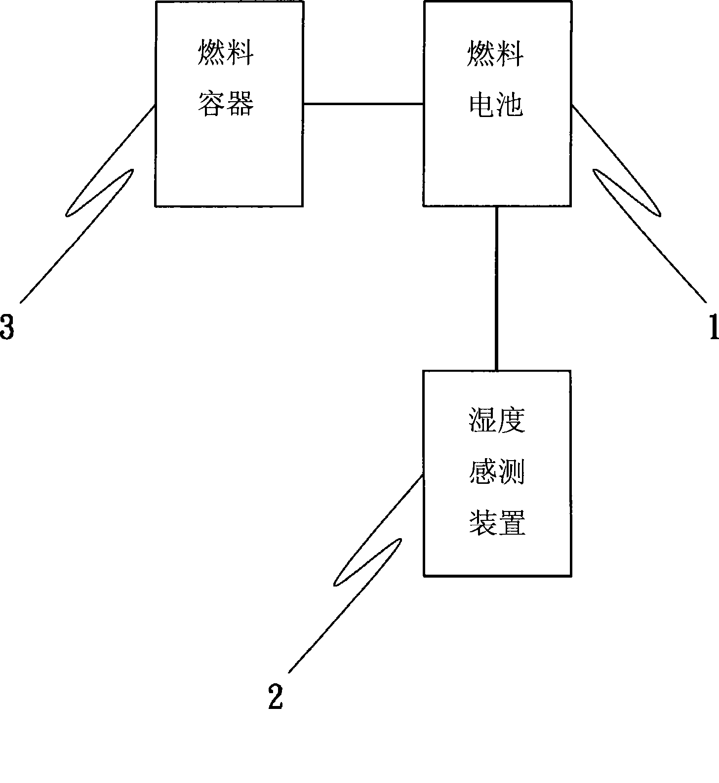
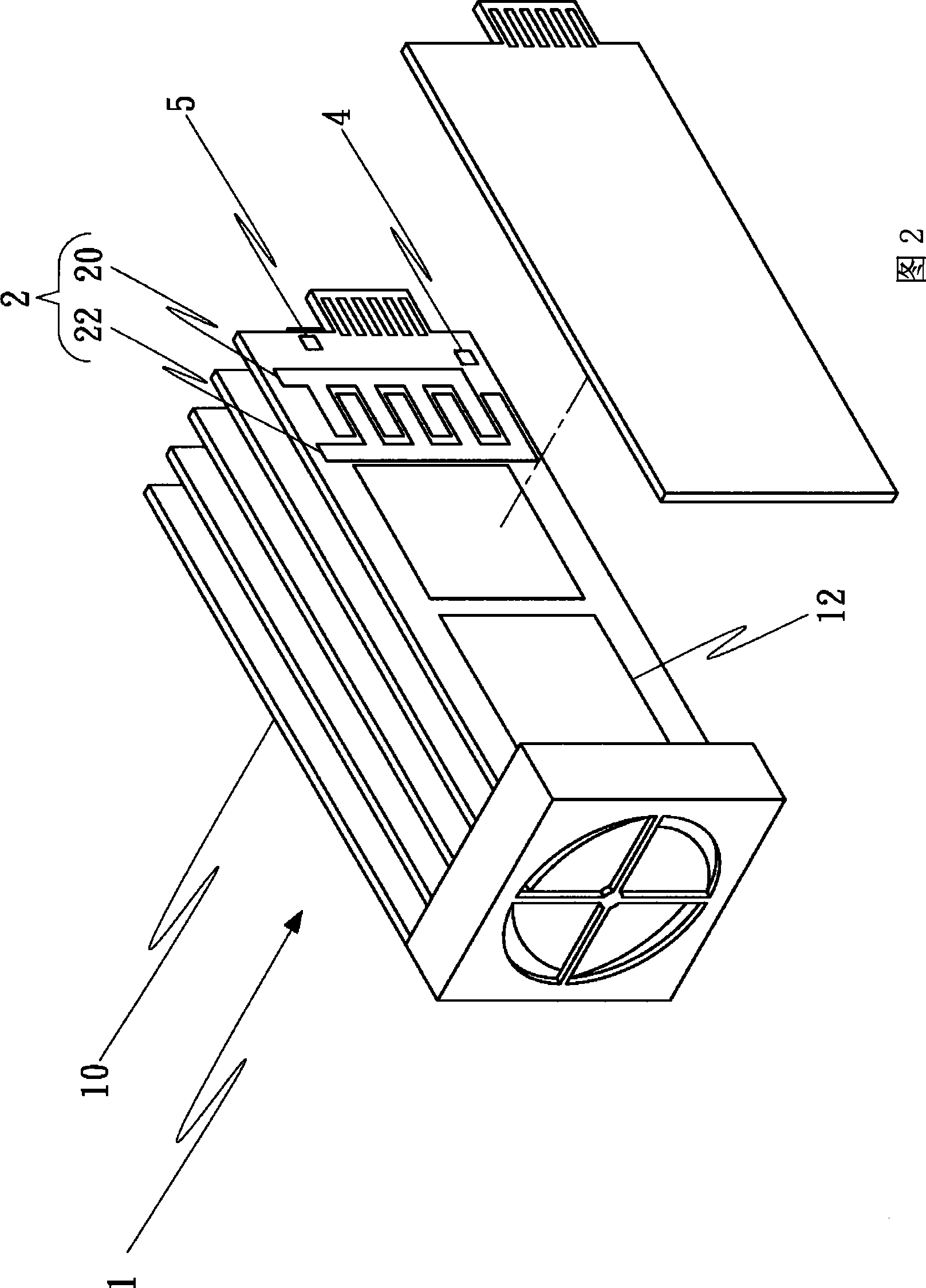
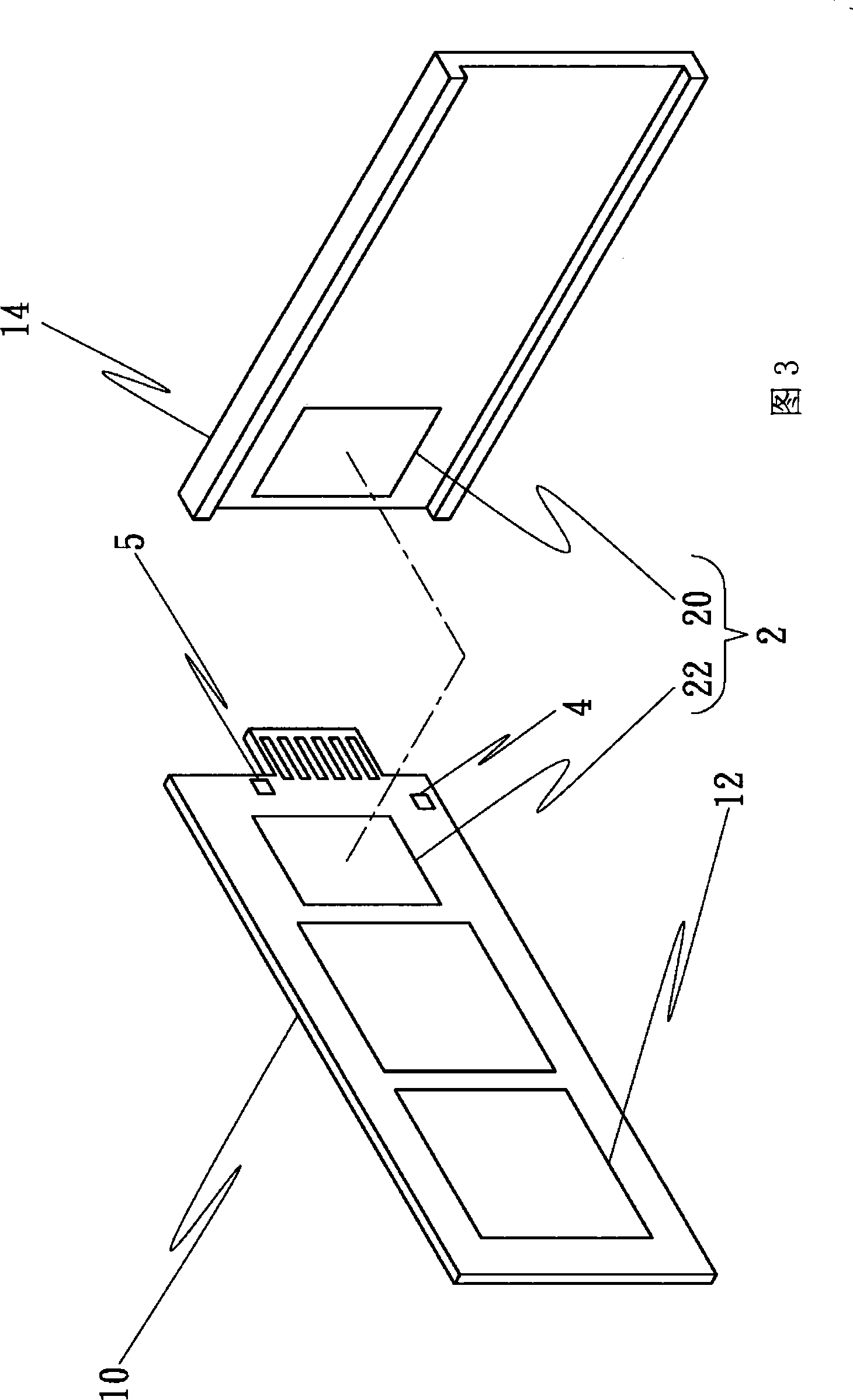
[0028] see figure 1 As shown, it is a component association diagram of a specific embodiment of the humidity sensing device of the present invention. The present invention provides a humidity sensing device, which is mainly used in a fuel cell system to illustrate a specific embodiment. It can be used in a fuel cell A sensing device 2 is arranged in the battery 1, and through the sensing device 2, the physical characteristics of the gas in the fuel cell 1, such as humidity, etc. are detected. Wherein, the fuel cell 1 is an energy converter that has a catalytic substance and can convert chemical energy into electrical energy output by chemically reacting with hydrogen-rich fuel and oxygen fuel; the fuel cell 1 must be able to store chemical reaction A fuel container 3 for the required fuel is used to provide fuel. The sensing device 2 is a sensing device for gas humidity, which has electrical metering means and data processing means. The electrical metering means is used to det...


PUM


Abstract

The invention provides a humidity sensing device which comprises a sensing device which includes an electric sensing method and a data processing method, wherein, the electric sensing method is used for detecting the electrical characteristics expressed by the gas due to humidity change, and the data processing method is used for treating electrical information detected by the electric sensing method to lead the electrical information to be converted into humidity information of the gas. The electric sensing method comprises a sensing element which includes a first metallic conduction parallel plate and a second metallic conduction parallel plate which are arranged in a corresponding way, so as to ensure the electrical information detected by the electric sensing method to be the capacitance value of the sensing element.

Description

technical field [0001] The invention relates to a humidity sensing device, in particular to a humidity sensing device capable of measuring humidity. Background technique [0002] The fuel cell currently used is mainly a fuel cell system that uses hydrogen-rich fuel fluid (such as methanol) to perform an electrochemical reaction with an oxygen-fuel fluid to output power. It is necessary to let the user know when the concentration of the fuel fluid is insufficient or the stock is insufficient However, the fuel fluid must be supplemented, but due to the improvement of technology, the efficiency of the fuel cell is getting more and more advanced, and its relative derivative problems are also coming one after another. [0003] Based on the above, one of the problems derived from the fuel cell is the change of humidity. The power generation device in the fuel cell is formed by stacking several circuit boards. Usually, when the power supply of the power generation device is large, ...

Claims


Application Information

Patent Timeline
IPC IPC(8): G01N27/22
Inventor 简永烈董敏耀
Owner SYSPOTEK CORP
Learn More