
Serial connector and transmission bridge of I*C cylinder manifold

A technology of serial connection and bridge, applied in the field of transmission bridge

Inactive Publication Date: 2009-06-03
INVENTEC CORP
View PDF0 Cites 0 Cited by
  • Summary
  • Abstract
  • Description
  • Claims
  • Application Information

AI Technical Summary

Problems solved by technology

However, there is currently no use of the serial port with the I 2 The transfer of information between the C bus as a technique for updating the firmware in the microcontroller

Method used

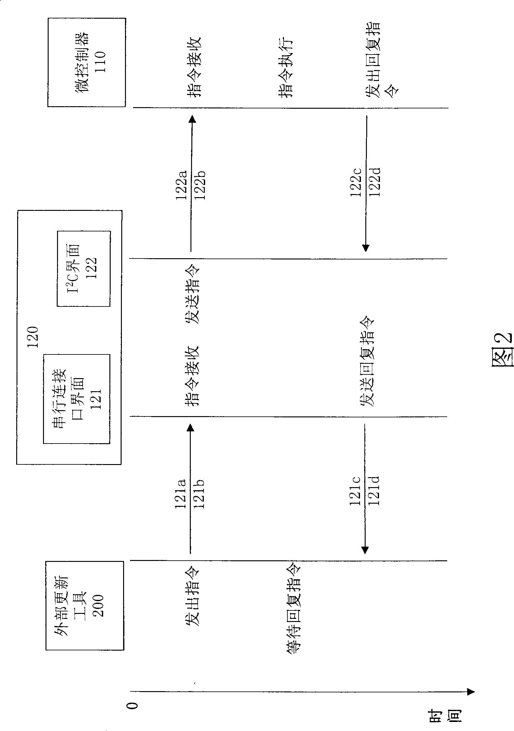

Image

  • Serial connector and transmission bridge of I*C cylinder manifold
  • Serial connector and transmission bridge of I*C cylinder manifold
  • Serial connector and transmission bridge of I*C cylinder manifold

Examples


Embodiment Construction

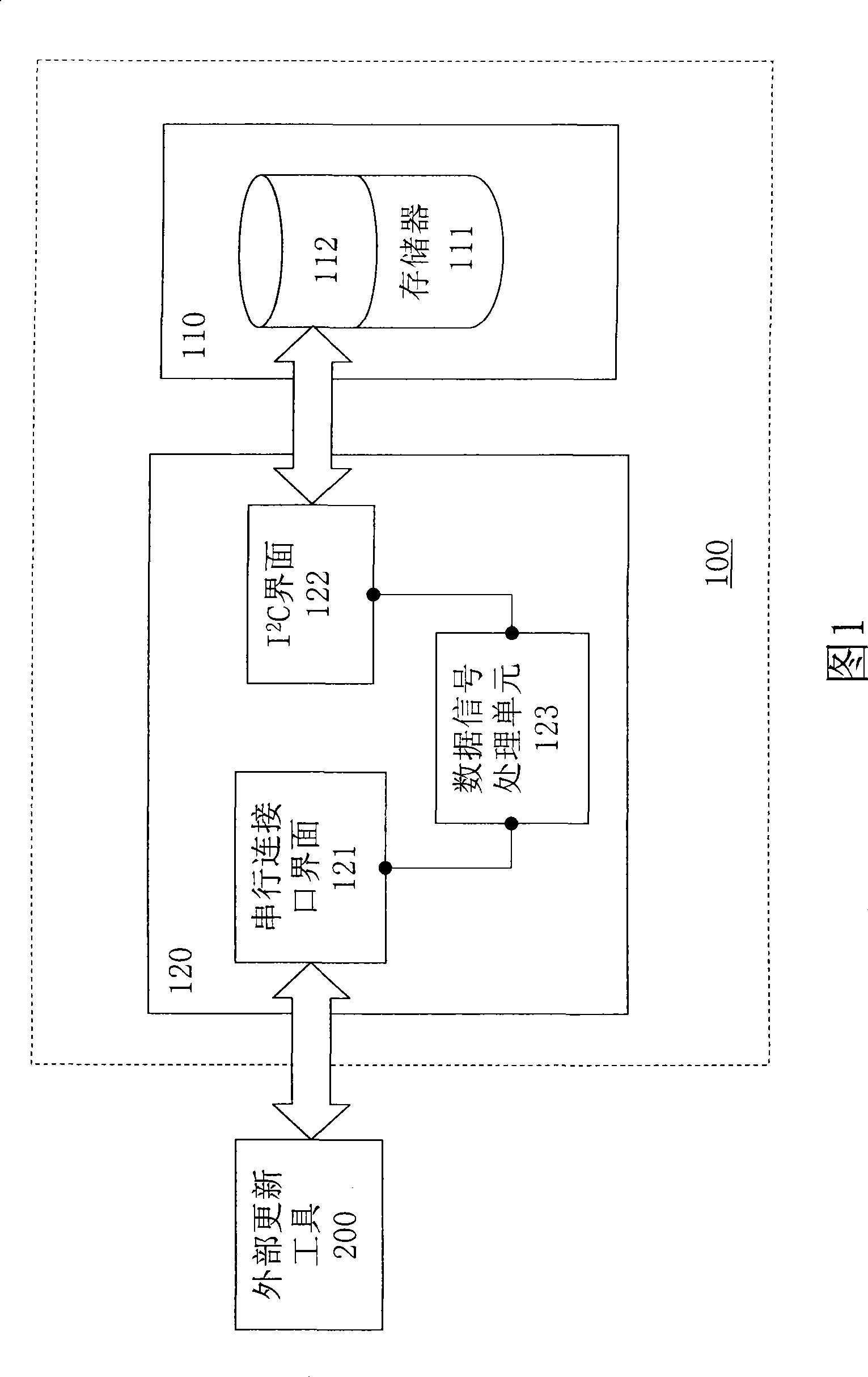
[0032] The present invention is a serial connection port and I 2 The transmission bridge of the C bus is especially applied to the system that can update the boot loader data in the boot block (Boot block). The content and technology of the present invention will be described in detail below in conjunction with a preferred embodiment of the technology of the present invention and accompanying drawings.

[0033] First of all, with reference to Fig. 1, it is the serial information and I of the present invention 2 Schematic diagram of the boot loader update system for C information transfer. As shown in Figure 1, the present invention has serial information and I 2 The bootloader (Bootloader) update system 100 for C information transmission is applied to update the firmware in a microcontroller 110 in the electronic device. The microcontroller 110 has a memory 111, and the memory 111 stores a firmware of a boot loader 112, which includes procedures and parameters for executing...


PUM


Abstract

A serial connector and a transmission bridge of an I <2>C cylinder manifold comprise a serial connector interface, an I <2>C interface, and a data signal processing unit so as to provide the conversion between a serial signal and a byte signal and the conversion between a serial data package and a byte data package.

Description

technical field [0001] The present invention relates to a serial port (Serial Port) and I 2 The invention relates to a transmission bridge for a C (Inter-Integrated Circuit) bus, in particular to a transmission bridge capable of converting and transmitting serial information and byte information. Background technique [0002] In the current microcontroller (Micro Control Unit, MCU), based on the consideration of functions and low cost factors, and to prevent the settings in the boot block (Boot block) from being modified, the jumper ( jumper) device to prohibit the process of writing to the start area of ​​the memory. Therefore, most technologies are not allowed to update the boot loader (Bootloader) in the boot block (Boot block). If the program version of the basic input / output system (BIOS) does not match the hardware resources of the main board and must be modified, or some of the stored startup programs or parameters need to be updated, at present, except for addition...

Claims


Application Information

Patent Timeline
IPC IPC(8): G06F13/38
Inventor 王宗斌
Owner INVENTEC CORP
Learn More