Magnetic-control wheel

A magnetic control wheel and structure technology, applied in the field of magnetic control wheels, can solve the problems of high manufacturing cost, poor movement quality, high transmission resistance, etc., and achieve the effects of reduced defective rate of finished products, low difficulty in mold manufacturing, and accurate positioning points

Inactive Publication Date: 2009-06-10
HER YUAN CHYUN
View PDF0 Cites 3 Cited by
  • Summary
  • Abstract
  • Description
  • Claims
  • Application Information

AI Technical Summary

Problems solved by technology

[0007] The purpose of the present invention is to provide a magnetic wheel structure to solve the problems of high manufacturing cost, poor movement quality and high transmission resistance due to the use of conical oblique meshing surface shape in the drive gear structure of the known magnetic wheel

Method used


Image

  • Magnetic-control wheel
  • Magnetic-control wheel
  • Magnetic-control wheel

Examples


Embodiment Construction

[0029] In order to enable those skilled in the art to better understand the solution of the present invention, and to make the above-mentioned purpose, features and advantages of the present invention more obvious and comprehensible, the present invention will be further described in detail below in conjunction with the accompanying drawings and embodiments.

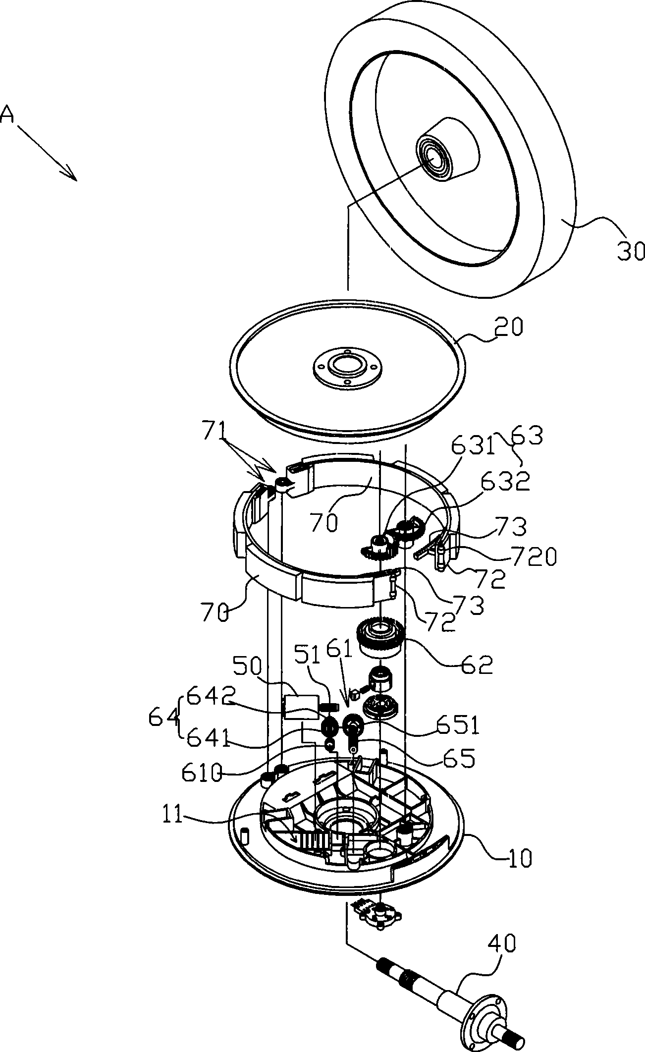
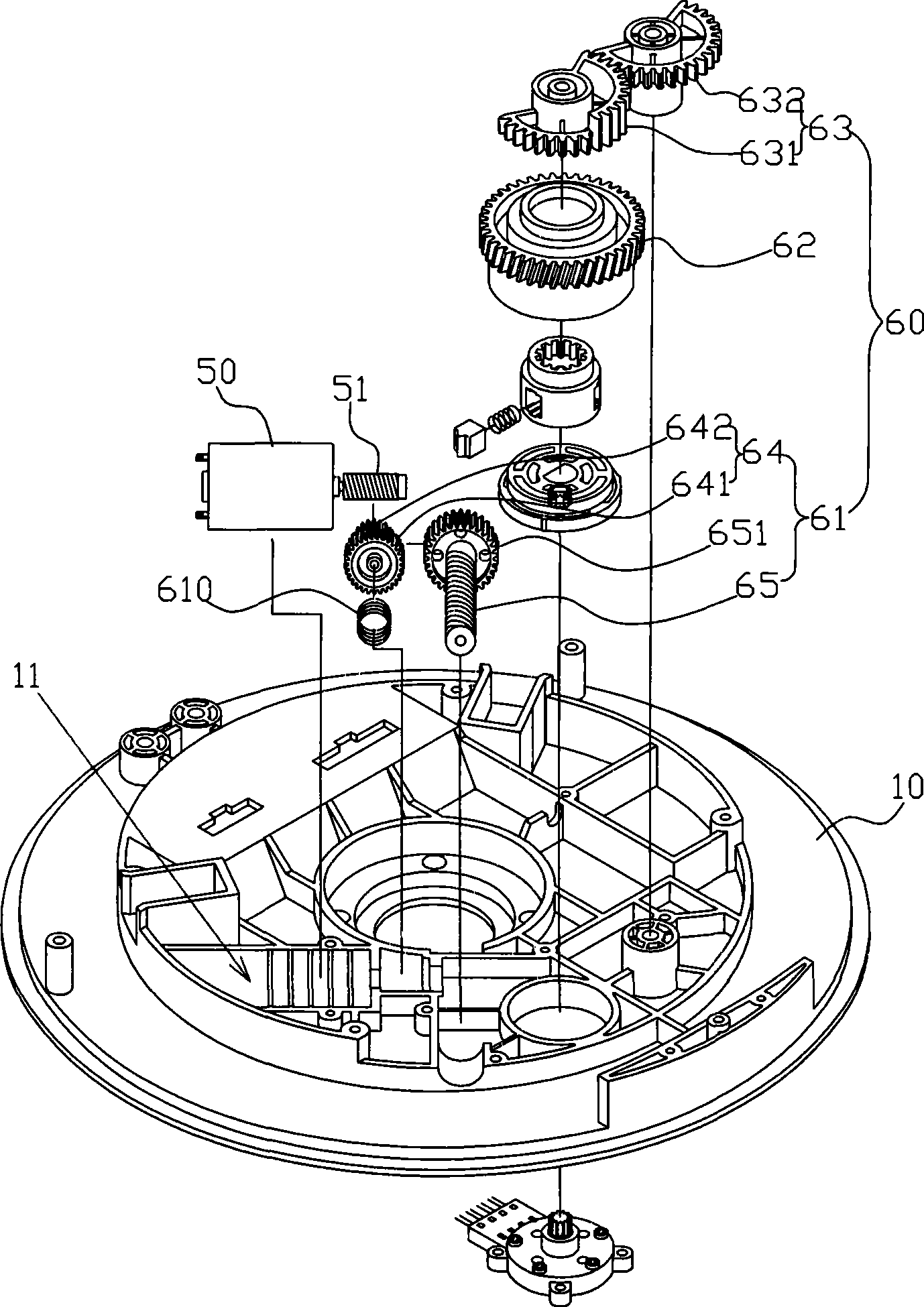
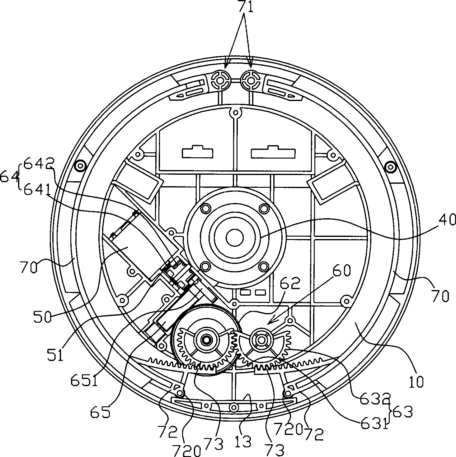
[0030] see Figure 1 ~ Figure 3 As shown, the preferred embodiment of the magnetic control wheel structure of the present invention, the magnetic control wheel A includes a base 10, a cover 20, a flywheel 30, a central shaft 40, a drive motor 50, a transmission gear set 60 And two magnetic control pieces 70; wherein, the pivot portion 71 of the two magnetic control pieces 70 is combined on the seat body 10 to form a swingable displacement at the bottom movable end 72 of the two magnetic force control pieces 70; the seat body 10 is equipped with The space 11 is for the drive motor 50 and the transmission gear set 60 to be...


PUM


Abstract

The invention discloses a magnetic control wheel configuration for solving problem of high cost, poor action quality and high transfer resistance of the magnetic control wheel driving gear mechanism by using oblique cone mating surface shape; the magnetic control wheel includes a base body, a cover body, a flying wheel, a center axis, a driven motor, a transfer gear group and two magnetism control pieces; the transfer gear group includes a speed change turning group, an interlock piece and a rear gear; a setting axial direction of the interlock piece and the rear gear is same with the magnetic control center axis; a gear row set by two magnetism control pieces mesh transmit with the rear gear together, a spur gear meshing shape is in between the rear gear and the gear row set by the magnetic control piece; a spring component is top braced between one axial end of the speed change turning group of the transfer gear group and one resistance piece of the base body containing space mutually. The magnetic control wheel configuration can be used in sports facility configuration.

Description

technical field [0001] The invention relates to a resistance control device, in particular to a magnetic control wheel applied to the structure of sports and fitness equipment. Background technique [0002] The magnetic control wheel is a resistance control device applied to the structure of sports and fitness equipment. The working principle of the magnetic control wheel is mainly to drive the two control pieces to swing relative to each other through the driving device and the linkage member. The control piece is provided with a magnet and the magnetic ring set by a flywheel is opposite to each other. Therefore, through the swing of the control piece, it can be adjusted. The strength of the magnetic field can be adjusted to achieve the purpose of adjusting the resistance of the flywheel. [0003] In the structure of the magnetic control wheel, as far as the interlocking member driving the two regulating pieces is concerned, it is common to use a gear set to drive the corr...

Claims


Application Information

Patent Timeline
Patent Type & Authority Applications(China)
IPC IPC(8): A63B21/005A63B21/22
Inventor 林宪模
Owner HER YUAN CHYUN
Why Eureka
Try Eureka