Numerical control pneumatic engine

A pneumatic engine and cylinder technology, applied in the field of powertrain, can solve the problems of high pressure air pressure energy loss, complex engine air distribution mechanism, difficult gas flow control, etc., to eliminate frost and ice blockage, easy control, energy Efficient effect

Inactive Publication Date: 2009-06-10
JIANGSU UNIV
View PDF3 Cites 19 Cited by
  • Summary
  • Abstract
  • Description
  • Claims
  • Application Information

AI Technical Summary

Problems solved by technology

[0004] The purpose of the present invention is to address the energy crisis and the deterioration of the human living environment brought about by the large number of applications of internal combustion engines at present, as well as the frosting and ice blockage of heat exchangers caused by the expansion and heat absorption of high-pressure gas in the pipeline during the use of traditional pneumatic engines and other problems, and it is difficult to control the gas flow rate, the pressure energy loss of high-pressure air is large, the utilization efficiency is low, the gas distribution mechanism of the engine is complicated, the manufacturing process requirements are high and the control is difficult, and a numerical control pneumatic engine is provided.

Method used


Image

  • Numerical control pneumatic engine

Examples


Embodiment Construction

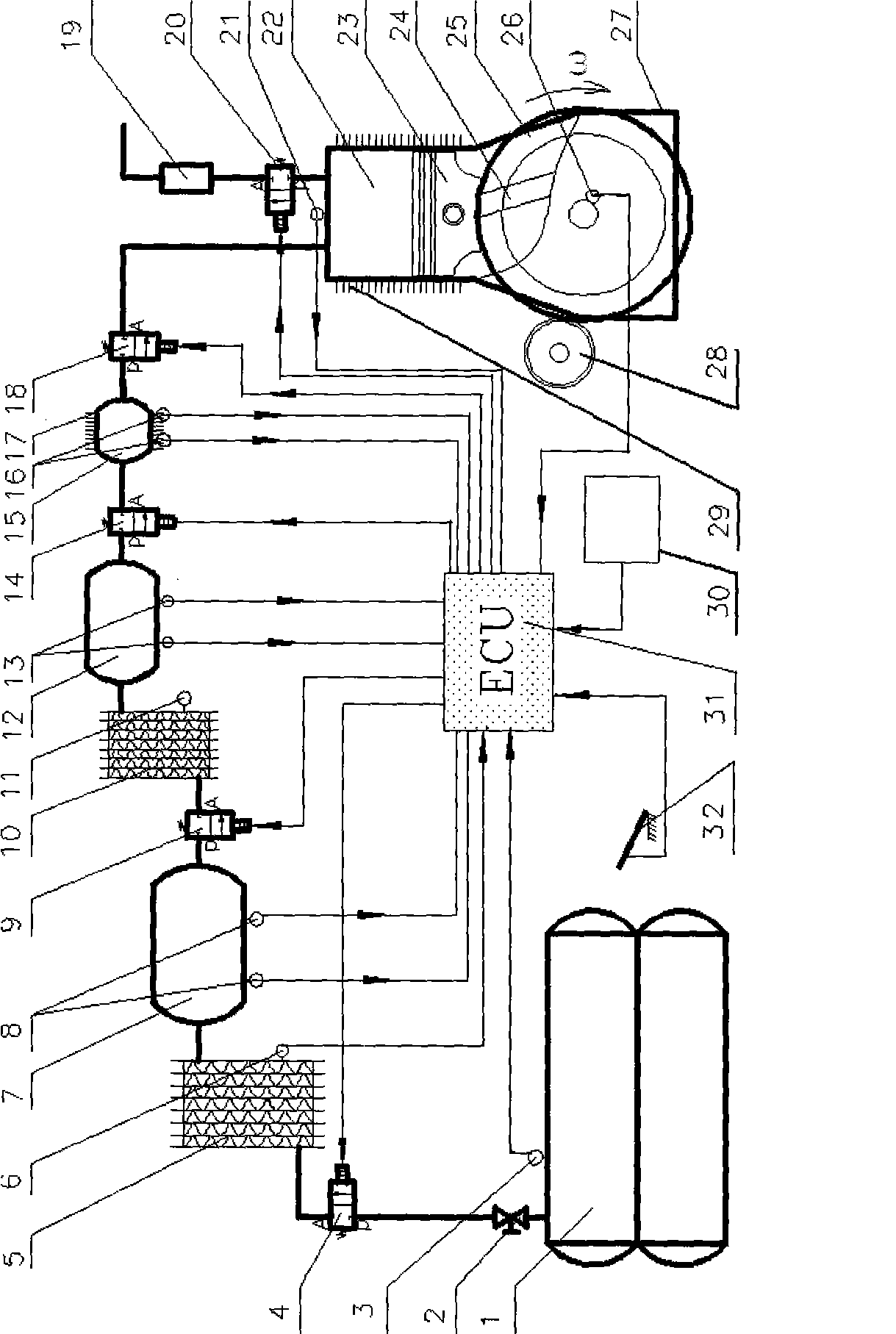
[0014] Such as figure 1 , the CNC pneumatic engine is mainly composed of three major systems: energy supply system, energy conversion system and control system, and its working process mainly includes: energy supply process and energy conversion process.

[0015] 1. Energy supply process

[0016] The energy supply system of the CNC pneumatic engine consists of a high-pressure gas storage tank 1, a manual valve 2, a control solenoid valve A 4, a primary heat exchanger 5, a primary decompression cylinder 7, a control solenoid valve B 9, and a secondary heat exchanger 10 , two-stage decompression cylinder 12, control solenoid valve C 14, quantitative pre-spray cylinder 15, and control solenoid valve D 18 are sequentially connected in series by relevant pipelines. The control system is composed of electronic control unit 31, signal acquisition equipment and execution equipment. Wherein the signal acquisition equipment includes various temperature, pressure and position sensors a...


PUM


Abstract

The invention discloses a numerical control pneumatic engine, which comprises an energy supply system, an energy conversion system and a control system. The energy supply system consists of a high-pressure air storage tank, a manual valve, a control electromagnetic valve A, a primary heat exchanger, a primary decompression cylinder, a control electromagnetic valve B, a secondary heat exchanger, a secondary decompression cylinder, a control electromagnetic valve C, a quantitative pre-spraying cylinder and a control electromagnetic valve D which are connected in series by pipelines. The energy conversion system comprises a body; a working cylinder is connected with a crank gear through a piston; and a fly wheel is connected with the other end of the crank gear. The control system consists of an electronic control unit, a signal acquisition device and an execution device. The numerical control pneumatic engine uses compressed air or liquid nitrogen, and has the characteristics of no pollution, convenient storage and transportation, simple manufacturing process, high energy efficiency, convenient control and the like, and can be used as a power source for daily short traffic or indoor traffic tools in seriously polluted cities.

Description

technical field [0001] The invention relates to a numerically controlled compressed air or liquid nitrogen power engine used for automobile power, belonging to the field of power trains. Background technique [0002] Automobiles mainly consume fossil fuels such as gasoline, diesel and natural gas as the source of power, and at the same time emit CO to the outside world. x , NO x and CH x Exhaust gases such as harmful substances. While the automobile industry brings vigorous vitality to the economy, it also brings energy crisis and environmental pollution to human society. The depletion of various fossil energy sources has forced more and more people to start exploring new energy sources, and green concept cars in the name of new energy sources have appeared one after another. Compressed air power engine is exactly a typical example of a kind of non-polluting emission green car that conforms to this trend. [0003] The patent No. is 01108350.6, and the patent disclosed b...

Claims


Application Information

Patent Timeline
Patent Type & Authority Applications(China)
IPC IPC(8): F01B17/02F01B21/02
Inventor 陈士安徐建军何仁刘红光陆森林
Owner JIANGSU UNIV
Why Eureka
Try Eureka