Floating wave power machine

A wave power machine and floating technology, applied in the field of floating wave power machine, can solve the problems of easy damage, difficulty in mooring, undeveloped wave power generation, etc., and achieve the effect of high power generation efficiency

Inactive Publication Date: 2009-06-10
梁运富
View PDF0 Cites 5 Cited by
  • Summary
  • Abstract
  • Description
  • Claims
  • Application Information

AI Technical Summary

Problems solved by technology

[0002] In the past, wave power generation devices were generally fixed. When the waves were strong, they were difficult to moor and easily damaged, so wave power generation could not be developed. This is its biggest weakness.

Method used


Image

  • Floating wave power machine
  • Floating wave power machine
  • Floating wave power machine

Examples


Embodiment Construction

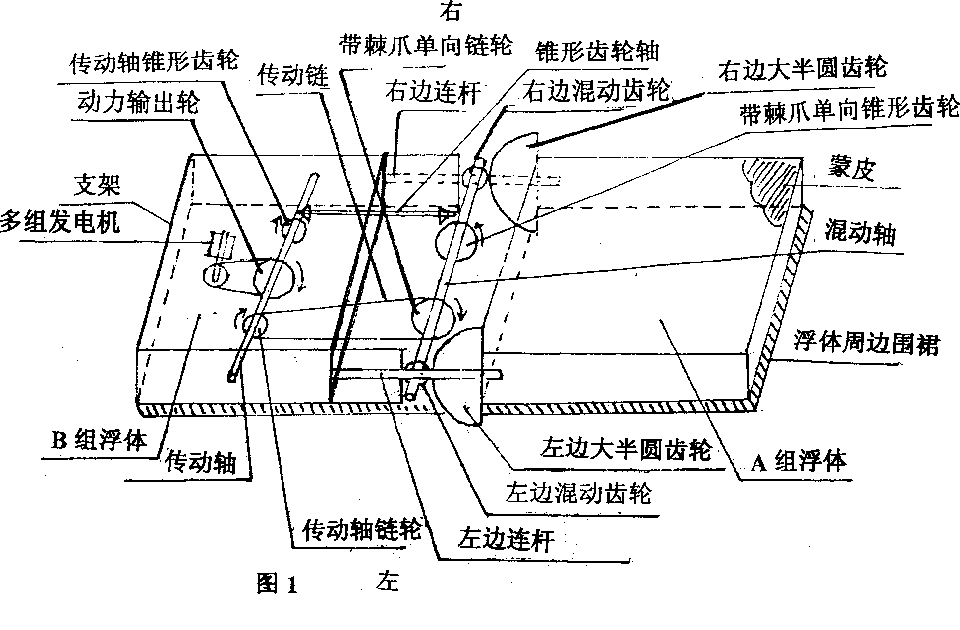
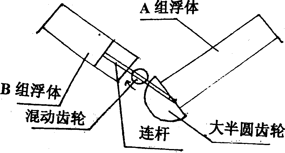
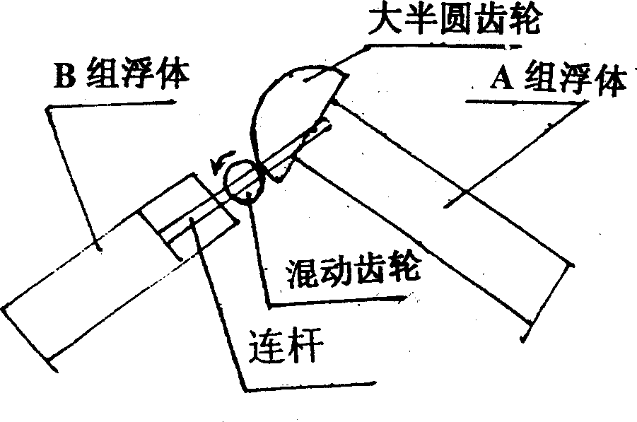
[0012] See Figure 1- figure 2 one image 3 , the floating wave force machine has a flat square structure, large semicircular gears, hybrid gears, connecting rods are installed on both sides of the two sets of floating bodies, hybrid shafts, one-way gears, transmission shafts, transmission couplings, and bevel gear shafts , power output wheel, and multiple sets of generators are installed in the buoyant support of group B, and the apron is installed under the periphery of the floating body. The two groups of floating bodies are uplifted or collapsed by waves to form a ∧ or ∨ shape, so that the hybrid gear moves back and forth along the large semicircular gear To obtain positive and negative rotation, drive two sets of one-way gears and a transmission chain, and the bevel gear shaft through the hybrid shaft to obtain one-way rotation of the transmission shaft to output power for power generation.


PUM


Abstract

The present invention discloses a floating wave force machine that mainly collects wave energy. Two groups of floating body include a support, a big semi-circle wheel gear, a mixed axle, a side rod, a one-way wheel gear, a mixed gear, a drive chain, a angular wheel axis, a drive capstan, a power take-off wheel, multi-group generators, a thin-gauge skin and a apron compose a floating wave force machine which is put on a sea surface with certain wave height and obtain power take-off along with wave rise and fall to generate power. The present invention has broad adaptability and high efficiency, can be applied on sea surface with certain wave height particularly on power generation of sailing ships and offshore operation which can be moved, delivered or retracted anytime.

Description

technical field [0001] The invention is mainly used as a wave machine for collecting wave energy, and is especially suitable for a floating wave machine for continuous power generation from wave energy on an ocean surface with a certain wave height. Background technique [0002] In the past, wave power generation devices were generally fixed. When the waves were strong, they were difficult to moor and easily damaged. Therefore, wave power generation cannot be developed, which is its biggest weakness. Contents of the invention [0003] The problem to be solved by the present invention is to provide a floating wave machine that can move and float on the ocean water surface and directly use wave energy to generate electricity. Large semicircular gear, hybrid shaft, hybrid gear, connecting rod, one-way gear with pawl, transmission chain, bevel gear shaft, transmission shaft, power output wheel, multiple sets of generators, skins, and aprons. Two pairs of large semicircular ge...

Claims


Application Information

Patent Timeline
Patent Type & Authority Applications(China)
IPC IPC(8): F03B13/16H02K7/18
CPCY02E10/38Y02E10/30
Inventor 梁运富
Owner 梁运富
Why Eureka
Try Eureka