
Liquid air engine

A technology of power machine and liquid air, which is applied in the direction of variable displacement engine, machine/engine, reciprocating piston engine, etc., can solve the problems of unreached, unsatisfactory results, and low energy efficiency of liquid nitrogen, so as to improve work efficiency, The effect of small energy loss and good power output effect

Active Publication Date: 2013-01-30
王润湘
View PDF5 Cites 0 Cited by
  • Summary
  • Abstract
  • Description
  • Claims
  • Application Information

AI Technical Summary

Problems solved by technology

[0003] Relevant institutions and university research groups around the world are developing liquid nitrogen engines, that is, equipment that uses liquid nitrogen and liquid air to generate power, but the prototypes that have been developed so far have not yet reached the practical level. Engines are used as power for automobiles. Japan is also developing liquid nitrogen engines for automobiles, but the results are not ideal. The key is that the energy efficiency of liquid nitrogen used in liquid nitrogen engines is not high. One of the main problems that needs to be solved is how to Improve the energy release in liquid air or liquid nitrogen and solve the problem of frosting when liquid nitrogen vaporizes

Method used


Image

  • Liquid air engine
  • Liquid air engine
  • Liquid air engine

Examples


Embodiment Construction

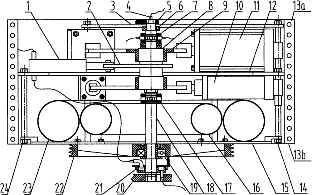
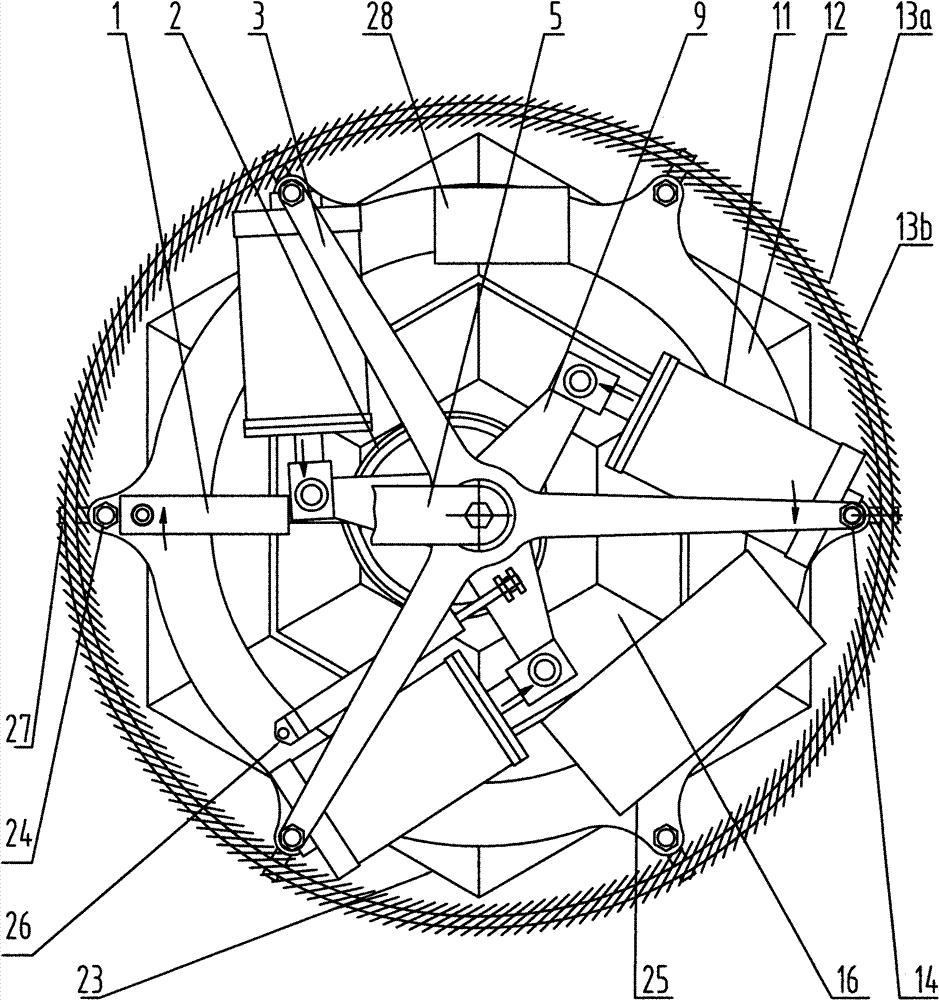
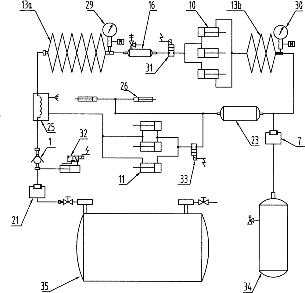
[0021] In accompanying drawing 1: upper bearing (5), lower bearing (20) are the fixed bearings of liquid-pneumatic power machine, fix central shaft (18) from upper end and lower end, and central shaft (18) is fixed and cannot rotate during work of. The upper bracket (3) is installed on the middle shaft (18) through the upper bracket bearing (6), the lower bracket (15) is fixed on the main transmission wheel (22), and the main transmission wheel (22) passes through the main transmission wheel bearing (19) Installed on the central axis, the bracket fixes the short screw rod (24) and the bracket fixes the long screw rod (14) to connect the lower bracket (15), the middle support plate (12), and the upper bracket (3) into a rotatable integral bracket. Cam (2), external air source joint (4), gas joint (7), one-way overrunning clutch (8), movable electric contact (17), liquid gas joint (21) are fixedly installed on the central shaft (18). ). Rocking bar (9) is connected with one-wa...


PUM


Abstract

The invention relates to a liquid air engine. In the engine, an upper support (5) and a lower support (20) are fixed supports of the liquid air engine, a central shaft (18) is fixed from the upper end and the lower end, and the central shaft (18) is fixed and cannot be rotated in working; an upper bracket (3) is arranged on the central shaft (18) through an upper support bearing (6), and a lower bracket (15) is fixed on a main driving wheel (22); the main driving wheel (22) is arranged on the central shaft through a main driving wheel bearing (19); a bracket fixing short screw (24) and a bracket fixing long screw (14) are connected with the lower bracket (15), a middle support plate (12) and the upper bracket (3) to form a rotatable integral bracket; a cam (8), an external gas joint (4), a gas movable joint (7), a one-way overrunning coupler (8), a movable electric contact (17) and a liquid gas movable joint (21) are arranged on the central shaft (18); a rocker (9) and the one-way overrunning coupler (8) are in key connection to make clockwise one-way rotation; cylinder rodless end covers (in figure 4: 40) of a high-pressure cylinder group (10) and a low-pressure cylinder group (11) are fixed on the bracket fixing long screw (14), can make small swing around the bracket fixing long screw (14); the top of the cylinder piston rod is movably connected with the top of the rocker (9); the middle support plate is provided with a liquid nitrogen pump (1); and a high pressure vessel (16) and a low pressure vessel (23) are fixedly arranged on the lower bracket (15).

Description

Technical field [0001] The patent of the present invention relates to a device that uses liquid air or liquid nitrogen (hereinafter referred to as: liquid air or liquid nitrogen) to generate power, and a power device that can efficiently utilize liquid air or liquid nitrogen vaporization to perform work on compressed gas. [0002] At present, the secondary energy sources developed by people mainly include electric energy, hydrogen energy, compressed air and so on. Electric energy is the energy that uses electric motors to generate power, hydrogen energy is the energy that uses hydrogen fuel cells to generate electricity and then power, and compressed air is the energy that uses pneumatic components and equipment to generate power. Liquid air or liquid nitrogen is also a medium for energy storage. The energy in liquid air and liquid nitrogen is released by using the liquid air power machine. This is different from fuel-powered equipment, electric equipment and pneumatic equipme...

Claims


Application Information

Patent Timeline
Patent Type & Authority Patents(China)
IPC IPC(8): F01B17/02
Inventor 王润湘
Owner 王润湘
Learn More