Improved rotating ferromagnetic engine

A technology of rotary motion and engine, applied in the direction of generator/motor, mechanical equipment, vibration suppression adjustment, etc., can solve the problems of high-efficiency magnetic motor without reasonable shielding method of anti-interference

Inactive Publication Date: 2010-05-12
吴元
View PDF0 Cites 0 Cited by
  • Summary
  • Abstract
  • Description
  • Claims
  • Application Information

AI Technical Summary

Problems solved by technology

[0005] The search results show that there is no report of a high-efficiency magnetic motor with a real free movement (magnetic shielding motion system) and a reasonable shielding method for anti-interference.

Method used


Image

  • Improved rotating ferromagnetic engine
  • Improved rotating ferromagnetic engine
  • Improved rotating ferromagnetic engine

Examples


Embodiment Construction

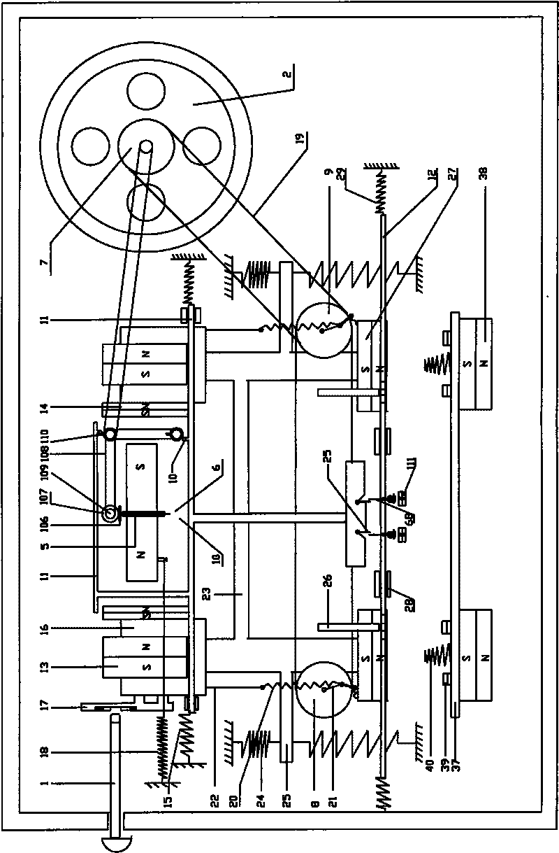
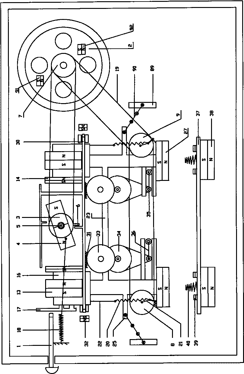
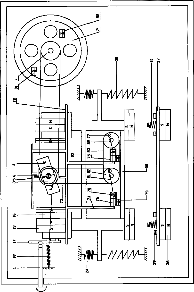
[0051] A ferromagnetic motor with a permanent magnet composite (see figure 1 , figure 2 , image 3 ,picture, Figure 5 , Figure 6 , Figure 7 ), consisting of a casing and an engine built into the casing.

[0052] The housing is provided with a start-stop knob 1, and the engine is composed of a power output system, an operation control system, a reaction force adjustment system, and a vibration reduction system.

[0053] The ferromagnetic motor is stopped by limiting the motion (of the overall motion system). When locking, the head of the start-stop knob should be inserted into the locking hole, and the locking hole can be on the U-shaped shielding block or on its appendage. The structure of the locking hole is that a compressible spring is respectively arranged on both sides of the locking hole on the straight line of its movement. This allows for a quick stop while avoiding shocks and vibrations. As shown in the attached body 17 of the U-shaped shielding block in ...


PUM


Abstract

The invention relates to a rotating ferromagnetic engine, comprising a casing and an engine arranged in the casing, and mainly solving the problems of energy shortage and environmental pollution caused by fossil fuel. The engine comprises a power outputting system, an operation control system, a gear engaging mechanism, a counterforce adjusting system and a damping system, wherein the power outputting system comprises a flywheel and a rotating permanent magnet; the operation control system comprises a syntonic spring, a mass block, a U-shaped shielding block, a control frame I with a movable baffle board, a control frame II with an opening, a piston slideway I, a piston slideway II, and a driving system I or a driving system II or a driving system III, and the piston slideway I and the piston slideway II are parallel to each other; and the counterforce adjusting system comprises a fixed partition board and a counterforce fixing permanent magnet. In addition, the engine further comprises a speed control system. The systems are mutually connected and generate kinetic energy through interaction, so that the improved rotating ferromagnetic engine can realize high-efficiency power output.

Description

technical field [0001] The invention relates to a magnetic energy motor, in particular to a rotating ferromagnetic motor. Background technique [0002] At present, the power devices used by humans include steam engines, internal combustion engines, and electric motors, all of which are power devices that convert electric energy, wind energy, water energy, and energy generated by coal, oil, and steam into mechanical energy. limit. Using the magnetic force of permanent magnets as a new energy source is still in the research and development stage. The ferromagnetic motor is a kinetic energy output device that organically combines permanent magnets and soft magnetic materials such as iron. At present, the engine related to magnetic energy is still in the research and development stage, the substantive key technology has not yet been broken through, and the output power is not efficient enough. [0003] There is a breakthrough in the current technology: that is, individual magn...

Claims


Application Information

Patent Timeline
Patent Type & Authority Applications(China)
IPC IPC(8): H02N11/00F16F15/00
Inventor 吴元
Owner 吴元
Why Eureka
Try Eureka