

Dual volume pump
A dual-capacity, capacity technology, applied in the direction of pumps, variable-capacity pump components, multi-cylinder pumps, etc., can solve the problem of inability to set the pump discharge capacity to zero, and achieve the effect of reliable pressure compensation
- Summary
- Abstract
- Description
- Claims
- Application Information
AI Technical Summary
Problems solved by technology
Method used
Image

Examples
Embodiment Construction
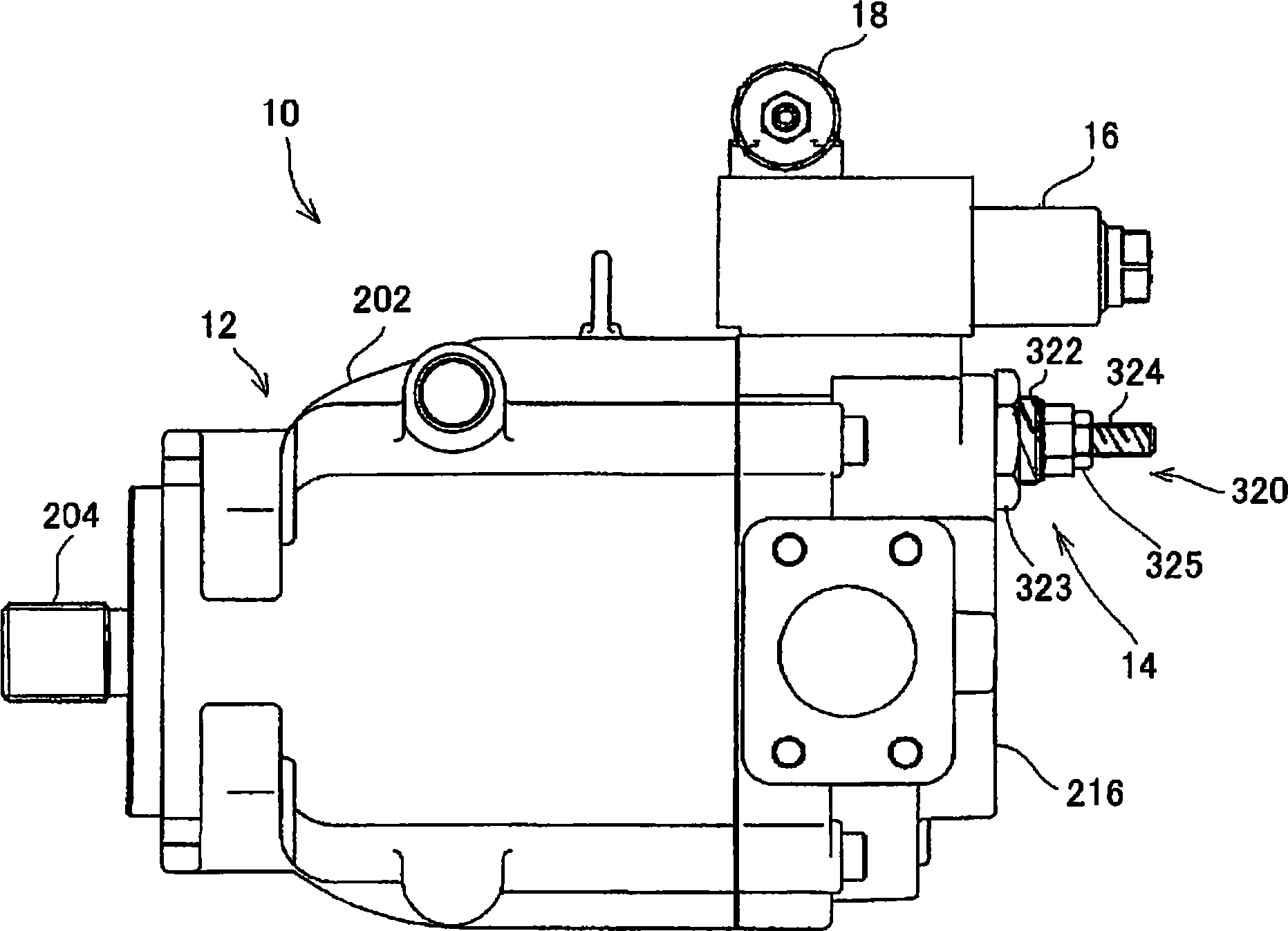
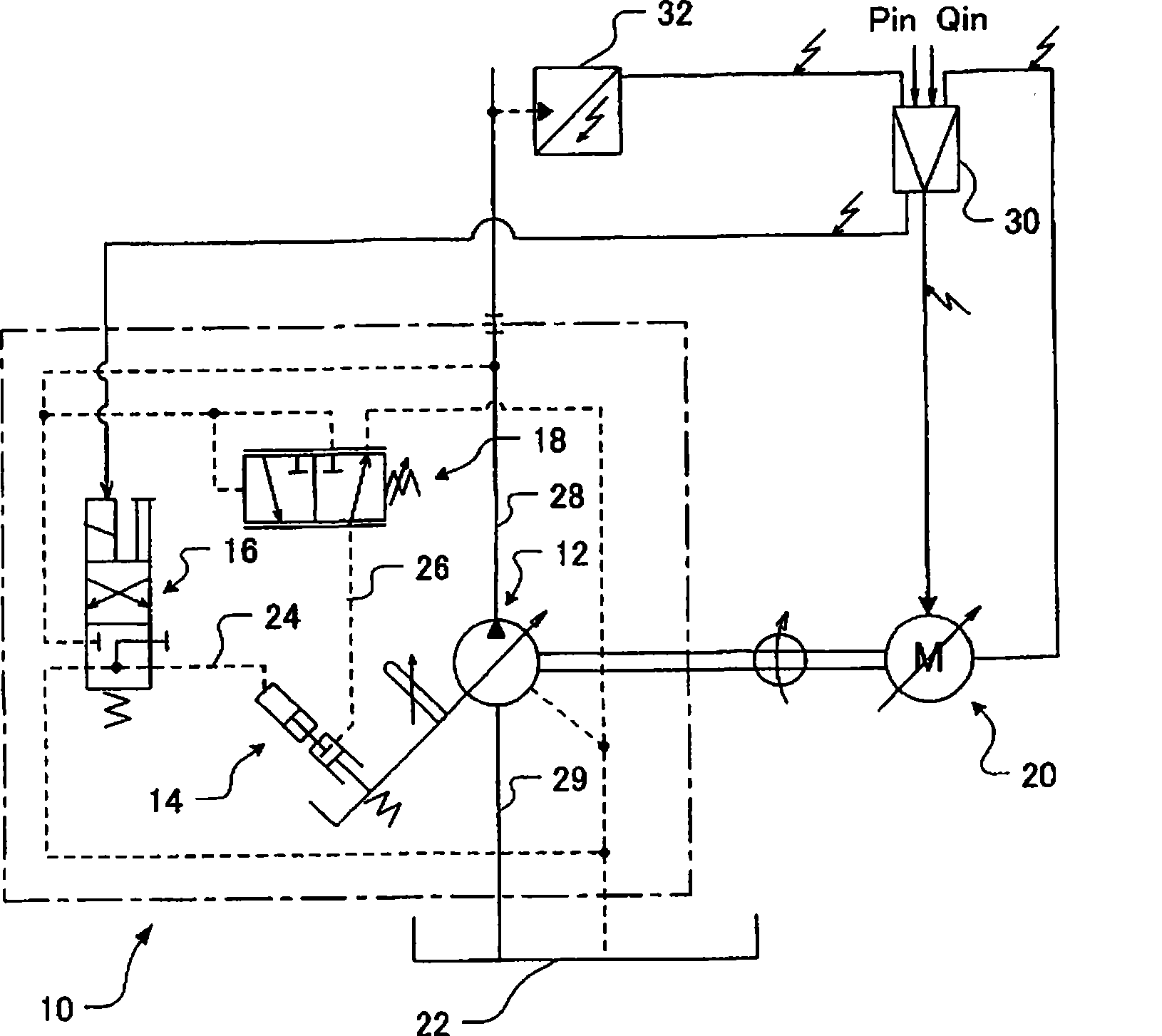
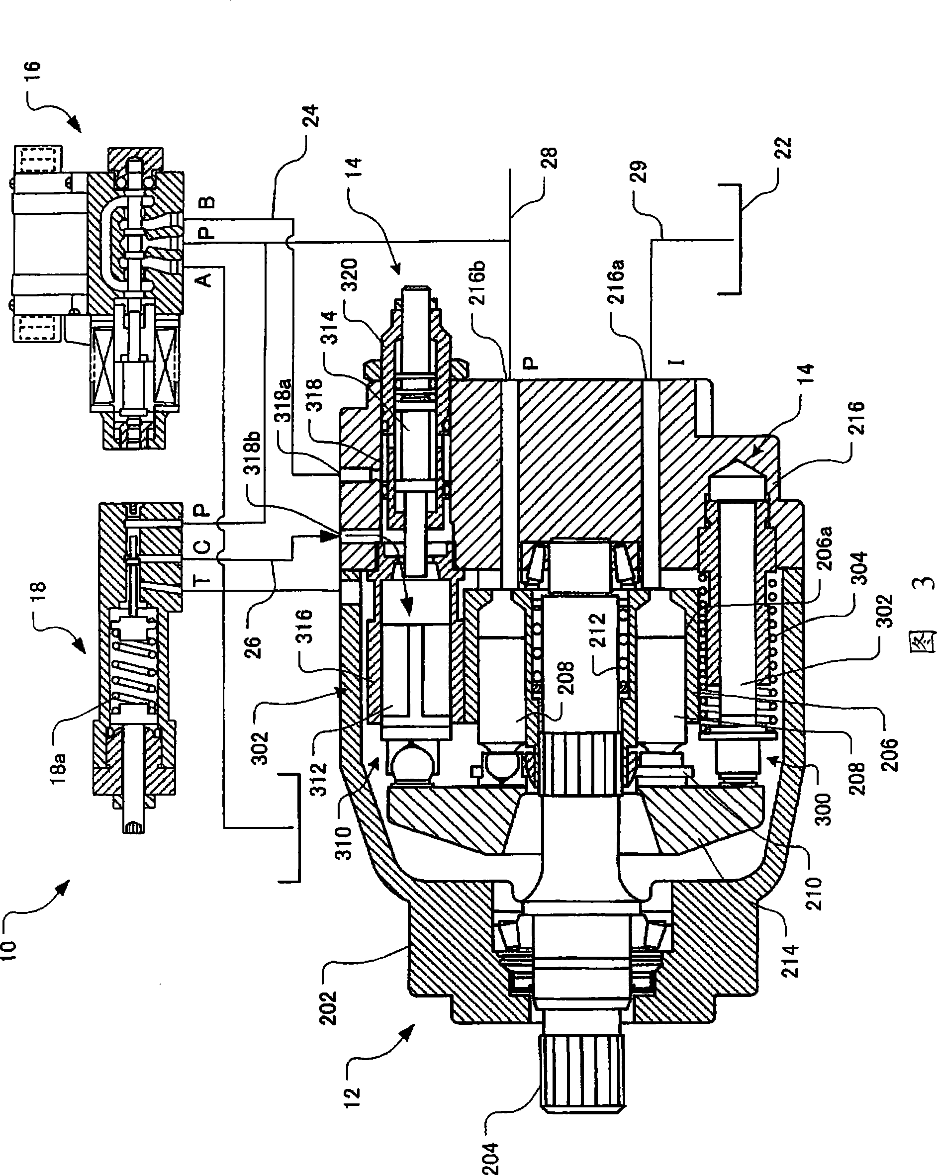
[0039] Embodiments of the present invention will be described below using the drawings. figure 1 is the appearance diagram of the double capacity pump of the present invention, figure 2 It is a circuit diagram, and Fig. 3 is a structural sectional view of the dual capacity pump.
[0040] exist figure 2Among them, the dual capacity pump 10 includes: a pump main body 12, which is rotationally driven to suck and discharge liquid; a variable capacity mechanism 14, which can change the discharge capacity per unit rotation of the pump main body 12; and a capacity switching valve 16, which The high-pressure side flow path and the low-pressure side flow path are selectively communicated with the pressure guide passage, and the pressure guide passage communicates with the pressure receiving part of the variable displacement mechanism 14, and the dual displacement pump 10 also has a pressure compensating mechanism. Compensation valve 18. The pump body 12 of the dual displacement p...
PUM
 Abstract
Description
Claims
Application Information