Method and apparatus for remediation of and recovery from a clutch slip event in a hybrid powertrain system

A clutch and powertrain technology, applied in the field of control systems of electro-mechanical transmissions, can solve problems such as negative effects on handling performance, acceleration changes, and emergency stops.

Active Publication Date: 2013-03-27
GM GLOBAL TECH OPERATIONS LLC
View PDF0 Cites 0 Cited by
  • Summary
  • Abstract
  • Description
  • Claims
  • Application Information

AI Technical Summary

Problems solved by technology

Sharp and uncoordinated changes in the various torques transmitted through the transmission cause undesired significant changes in vehicle acceleration or sudden stops, which can have a negative effect on the vehicle's handling characteristics

Method used


Image

  • Method and apparatus for remediation of and recovery from a clutch slip event in a hybrid powertrain system
  • Method and apparatus for remediation of and recovery from a clutch slip event in a hybrid powertrain system
  • Method and apparatus for remediation of and recovery from a clutch slip event in a hybrid powertrain system

Examples


Embodiment Construction

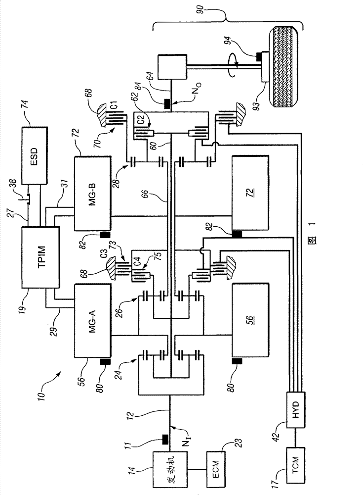
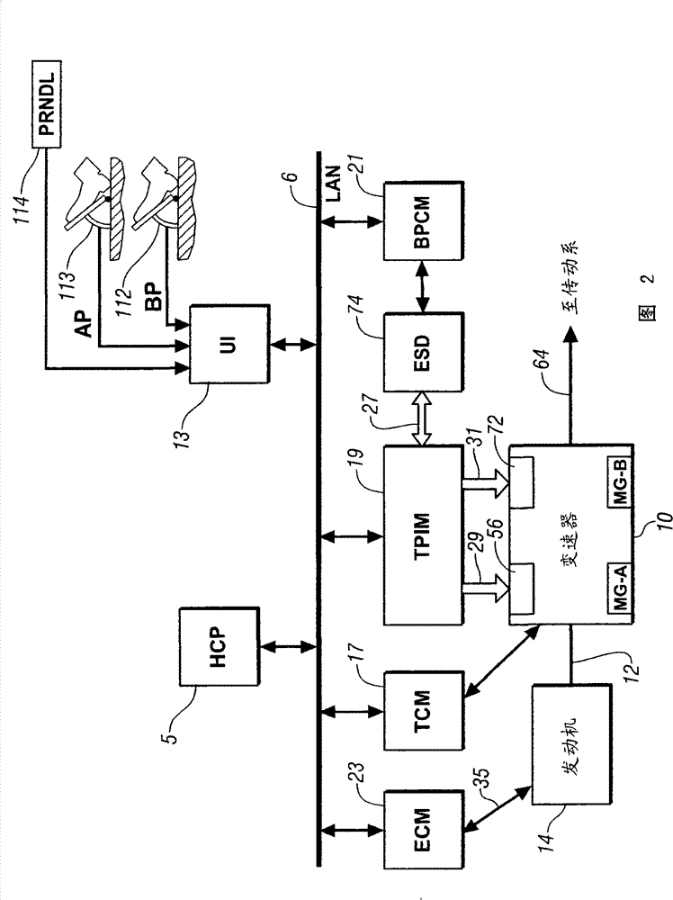
[0017] Referring now to the drawings, which are shown for purposes of illustration of certain exemplary embodiments only and not for purposes of limitation thereof, figure 1 and 2 An exemplary electro-mechanical hybrid powertrain is described. An exemplary electro-mechanical hybrid powertrain based on the present invention is in figure 1 , comprising a dual-mode, compound-split, electro-mechanical hybrid transmission 10 operative with an engine 14 and first and second electric machines ('MG-A') 56 and ('MG-B') 72 connect. The engine 14 and the first and second electric machines 56 and 72 respectively generate power that is transmitted to the transmission 10 . The power generated by the engine 14 and the first and second electric machines 56 and 72 while being transmitted to the transmission 10 is described in terms of input torque and speed, where the input torque is correspondingly represented as T I ,T A and T B , the velocity correspondingly expressed as N I , N A...


PUM


Abstract

A method for operating a powertrain, including an electro-mechanical transmission (10) mechanically-operatively coupled to an internal combustion engine (14) and an electric machine (56,72), includes monitoring slip across a selectively applied clutch (70,62,73,75) within the transmission (10) to indicate a clutch slip event, and if the monitoring indicates the clutch slip event decreasing a load across the selectively applied clutch (70,62,73,75) by reducing torque of at least one of the engine (14) and the electric machine (56,72), in order to reduce the slip, thereby ending the clutch slip event.

Description

[0001] For related applications see [0002] This application claims the benefit of US Provisional Application Serial No. 60 / 982458, filed October 25, 2007, the contents of which are hereby incorporated by reference. technical field [0003] The present invention relates to a control system for an electro-mechanical transmission. Background technique [0004] The statements in this section merely provide background information for the present invention and may not constitute prior art. [0005] Common powertrain architectures include torque-generative devices, including internal combustion engines and electric machines, that transmit torque through a transmission to an output member. An exemplary powertrain includes a dual-mode, compound-split, electro-mechanical transmission utilizing an input member to receive motive torque from a primary power source, preferably an internal combustion engine, and an output member. The output member can be operably connected with a powe...

Claims


Application Information

Patent Timeline
Patent Type & Authority Patents(China)
IPC IPC(8): F16H61/04F16H61/12F16H59/68F16H59/14
CPCY02T10/6286B60W2540/10B60W2540/12B60W10/06B60W2510/104B60W30/1846B60W10/02B60K6/547F16H2037/106B60K6/445B60L2240/421B60W30/20B60W2710/0666F16H2037/104B60W10/08B60L2240/441B60L2240/423Y02T10/6239F16H2037/102F16H2037/0866B60W2710/025F16H3/728B60L2240/486B60W2710/083B60K6/365B60W20/00B60K6/26B60W2710/1022B60K1/02B60W2510/0241Y02T10/642B60W2510/081B60W2510/0638Y02T10/62Y02T10/64B60W2050/0042B60W20/40
Inventor A·H·希普L·A·卡明斯基J·-J·F·萨
Owner GM GLOBAL TECH OPERATIONS LLC
Why Eureka
Try Eureka