

Circuit failure testing method, apparatus and single board
A technology of circuit failure and detection method, which is applied in the electronic field, can solve problems such as easy to cause false triggering, and achieve the effect of avoiding false detection and improving accuracy
- Summary
- Abstract
- Description
- Claims
- Application Information
AI Technical Summary
Problems solved by technology
Method used
Image

Examples
Embodiment 1
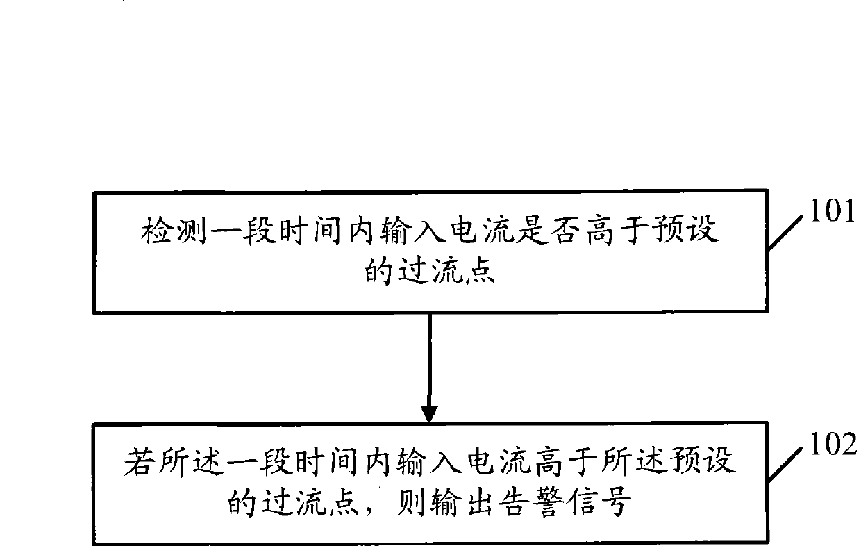
[0028] Such as figure 1 As shown, it is a schematic flowchart of a circuit fault detection method provided by Embodiment 1 of the present invention, which includes the following steps:
[0029] Step 101: Detect whether the input current is higher than a preset over-current point within a period of time.
[0030] Due to faults such as short circuits in the circuit, or due to factors such as power-on shocks and changes in external loads, the input current of the circuit will be overcurrent. The overcurrent point is the maximum input current value that the circuit can accept for normal operation of the circuit. The overcurrent point is generally predetermined according to the properties of the circuit.
[0031] This step is an implementation scenario, which can obtain the average value of the input current within a period of time after the input current of the circuit is higher than the overcurrent point, that is, the average input current during this period, and then detect whe...
Embodiment 2
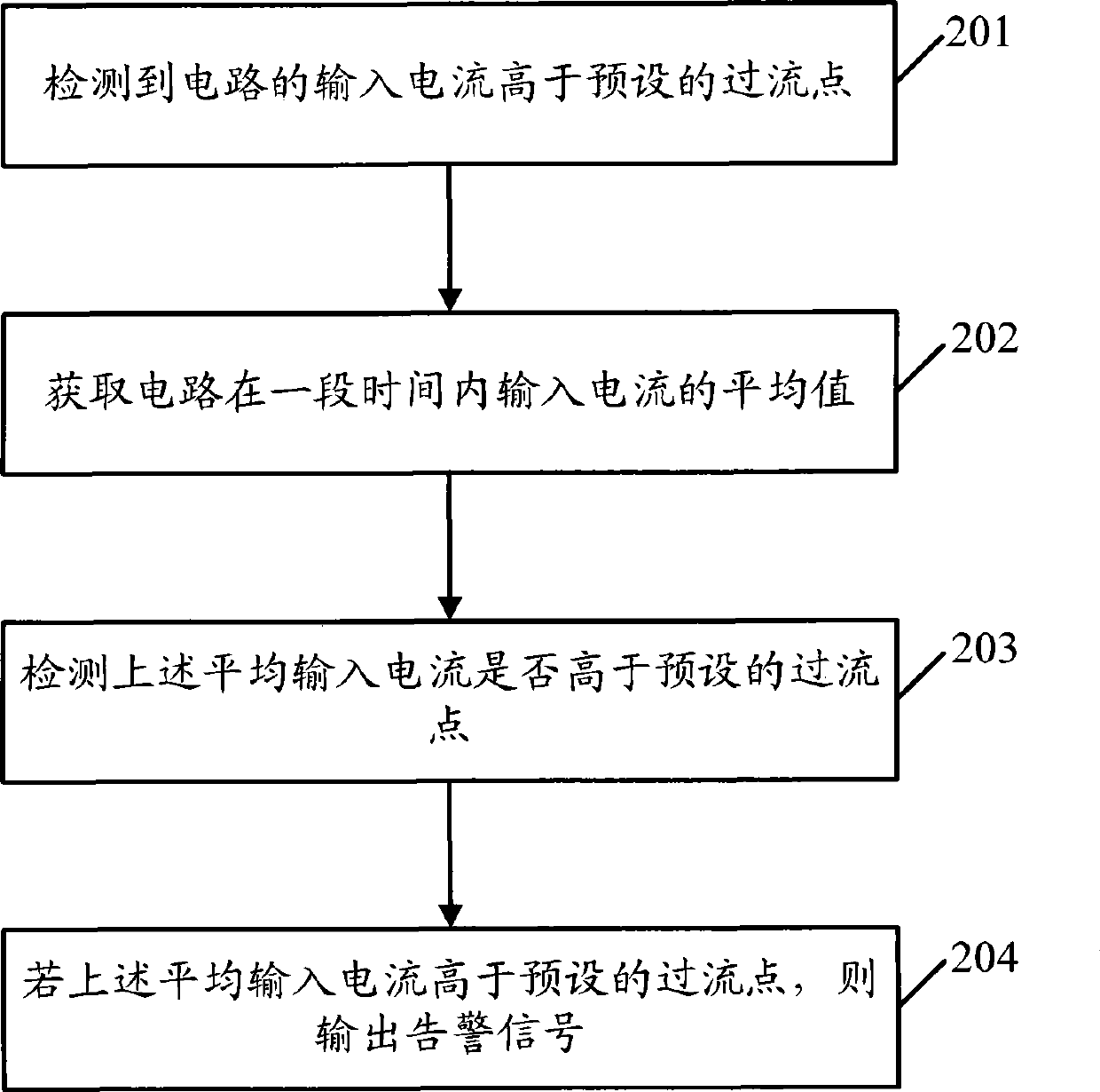
[0040] see figure 2 , is a schematic flowchart of a circuit fault detection method provided in Embodiment 2 of the present invention. In this embodiment, when it is detected that the input current of the circuit is higher than the preset overcurrent point, the The average input current, and will detect whether the average input current is higher than the overcurrent point to determine whether the circuit is faulty, including:
[0041] Step 201: Detecting that the input current of the circuit is higher than a preset overcurrent point;
[0042] Due to faults such as short circuits in the circuit, or due to power-on shocks, external load changes and other factors, the input current of the circuit will cause overcurrent. Therefore, an overcurrent point will be set first to further detect whether the input current is higher than the preset overcurrent point, wherein the overcurrent point is the maximum input current value that the circuit can accept in order to ensure the normal ...
Embodiment 3
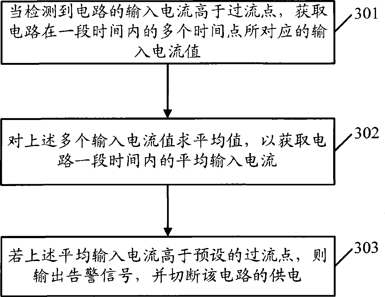
[0056] Such as image 3 As shown, it is a schematic flowchart of a circuit fault detection method provided by Embodiment 3 of the present invention. In this embodiment, how to obtain the average input current of a circuit within a period of time will be introduced, including the following steps:
[0057] Step 301: When it is detected that the input current of the circuit is higher than the overcurrent point, obtain the input current values corresponding to multiple time points of the circuit within a period of time.
[0058] Since the input current of the circuit is constantly changing, it is detected that the input current is higher than the overcurrent point at a certain moment in this step, for example, at t 1 It is always detected that the input current is higher than the overcurrent point, and the detection is from t 1 The average value of the input current during the time period T starting from time instant. The above-mentioned period of time T is a preset delay proc...
PUM
 Abstract
Description
Claims
Application Information