
Telescopic switching operation control system

A control system and switch operation technology, which is applied in the direction of electric switches, contact operating parts, electrical components, etc., can solve the problems of inconvenient operation of portable electronic equipment, and achieve the effect of increased height, easy operation, and convenient portability

Inactive Publication Date: 2009-06-10
武瑞桃
View PDF0 Cites 4 Cited by
  • Summary
  • Abstract
  • Description
  • Claims
  • Application Information

AI Technical Summary

Problems solved by technology

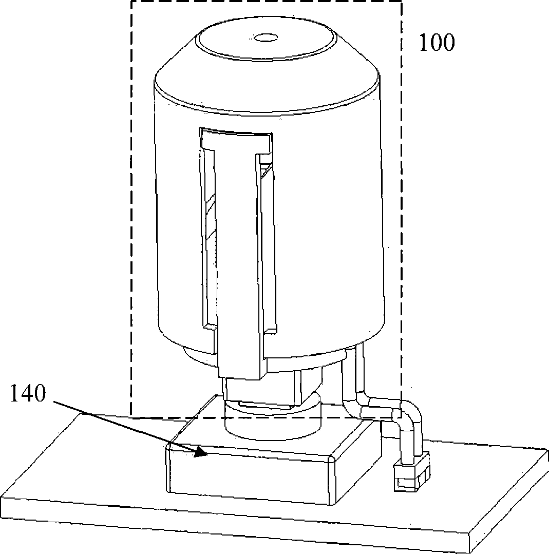
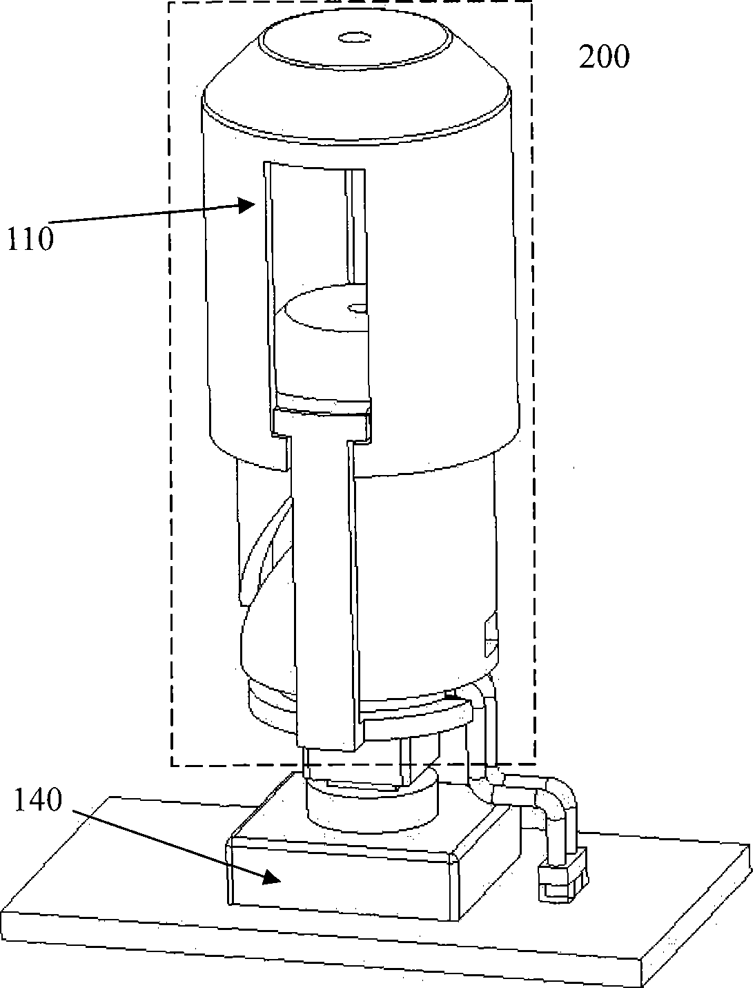
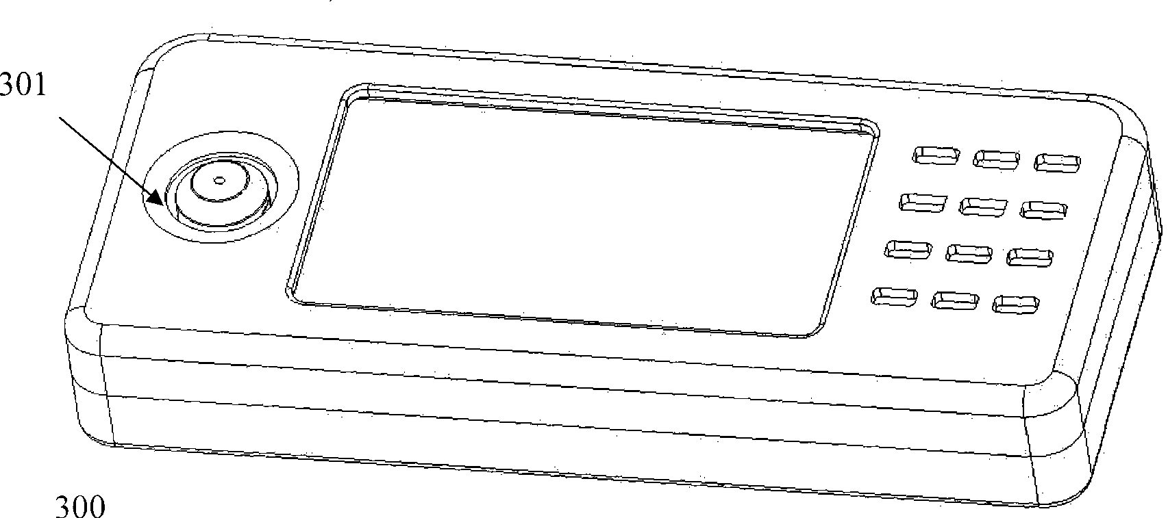
[0004] The invention provides a retractable switch operation control system, which overcomes the disadvantage of inconvenient direction operation of portable electronic equipment in the prior art, and at the same time retains the advantages of portable electronic equipment being easy to carry

Method used


Image

  • Telescopic switching operation control system
  • Telescopic switching operation control system
  • Telescopic switching operation control system

Examples


Embodiment

[0038] Figure 24 yes Figure 23 Implementing the Stretched State of an Instance

[0039] Figure 25 yes Figure 23 Exploded diagram of the parts of the implementation example

[0040] Figure 26 is Figure 23 The shrinkage state sectional view of the implementation example

[0041] Figure 27 is Figure 23 The stretched state sectional view of the implementation example

[0042] Figure 28 yes Figure 23 Implementation example motion part diagram

[0043] Figure 29 yes Figure 23 Schematic diagram of the magnet drive of the moving part of the implementation example

[0044] Figure 30 yes Figure 23 Schematic diagram of the action mechanism of the implementation example

[0045] Specific implementation

[0046] The present invention will be described in detail below in combination with the accompanying drawings and specific embodiments.

[0047] see figure 1 , provides a retractable switch operation control system 100 in a retracted state, through which the o...


PUM


Abstract

The invention relates to the field of portable electronic equipment and provides a switch operation control structure device for improving the human-machine interaction and the portability of electronic equipment. The invention discloses a telescopic operation control system, which consists of an operating lever, a motion part, and a fixing part; and a corresponding switch of the portable electronic equipment is controlled through the system. The operating lever can extend and retract relative to the telescopic operation control system so as to realize the operation of the operating lever relative to different height positions of the outer surface of the electronic equipment, and improve the operability and portability of the electronic equipment.

Description

technical field [0001] The invention relates to the field of portable electronic equipment, and more specifically relates to an operation control structure device for improving the man-machine interaction and portability of the electronic equipment. Background technique [0002] Many electronic devices, such as wireless phones, handheld computers, and handheld game consoles, all have buttons for directional operations, so as to realize different operations under various applications. Today's electronic equipment is developing towards a trend of diversified functions and small size. More functions such as game operation put forward further requirements for the human-computer interaction of electronic equipment, and at the same time, it is necessary to ensure that portable electronic equipment is easy to carry. [0003] The direction manipulation of many common electronic devices is realized by a direction key on the surface of the device and a membrane contact switch under it...

Claims


Application Information

Patent Timeline
IPC IPC(8): H01H3/02H01H3/20H01H25/00
Inventor 武瑞桃
Owner 武瑞桃
Learn More