
Method and apparatus for channel estimation

A technology of channel estimation and channel estimator, applied in the field of channel estimation, can solve problems such as performance degradation, high symbol error rate, and large amount of calculation, and achieve the effects of reducing complexity, narrowing performance differences, and increasing reliability

Inactive Publication Date: 2009-06-10
HUAWEI TECH CO LTD
View PDF0 Cites 2 Cited by
  • Summary
  • Abstract
  • Description
  • Claims
  • Application Information

AI Technical Summary

Problems solved by technology

The performance of this method has been improved for QPSK, but the inventor found in the process of implementing the embodiment of the present invention that due to the limited error correction capability in the decoding process, when the modulation order is high, If the number of bits used in the mapping process is >4, for example: the number of bits in each symbol of 16QAM is 4, and the number of bits in each symbol of 64QAM is 6. The process will have a high symbol error rate, so not only will it not improve performance, it may also cause performance degradation; after simulation verification, it is found that the performance of the above algorithm has declined in the 16QAM modulation mode
Moreover, in the above method, the soft demodulation in the iterative process has high complexity, and in general, the soft demodulation in the initial process and the soft demodulation in the iterative process use different formula decomposition methods to extract external information and participate in the iteration, so In the iterative process, the amount of calculation is large, and the storage space is increased to store the prior information and external information of the decoder.

Method used


Image

  • Method and apparatus for channel estimation
  • Method and apparatus for channel estimation
  • Method and apparatus for channel estimation

Examples


Embodiment Construction

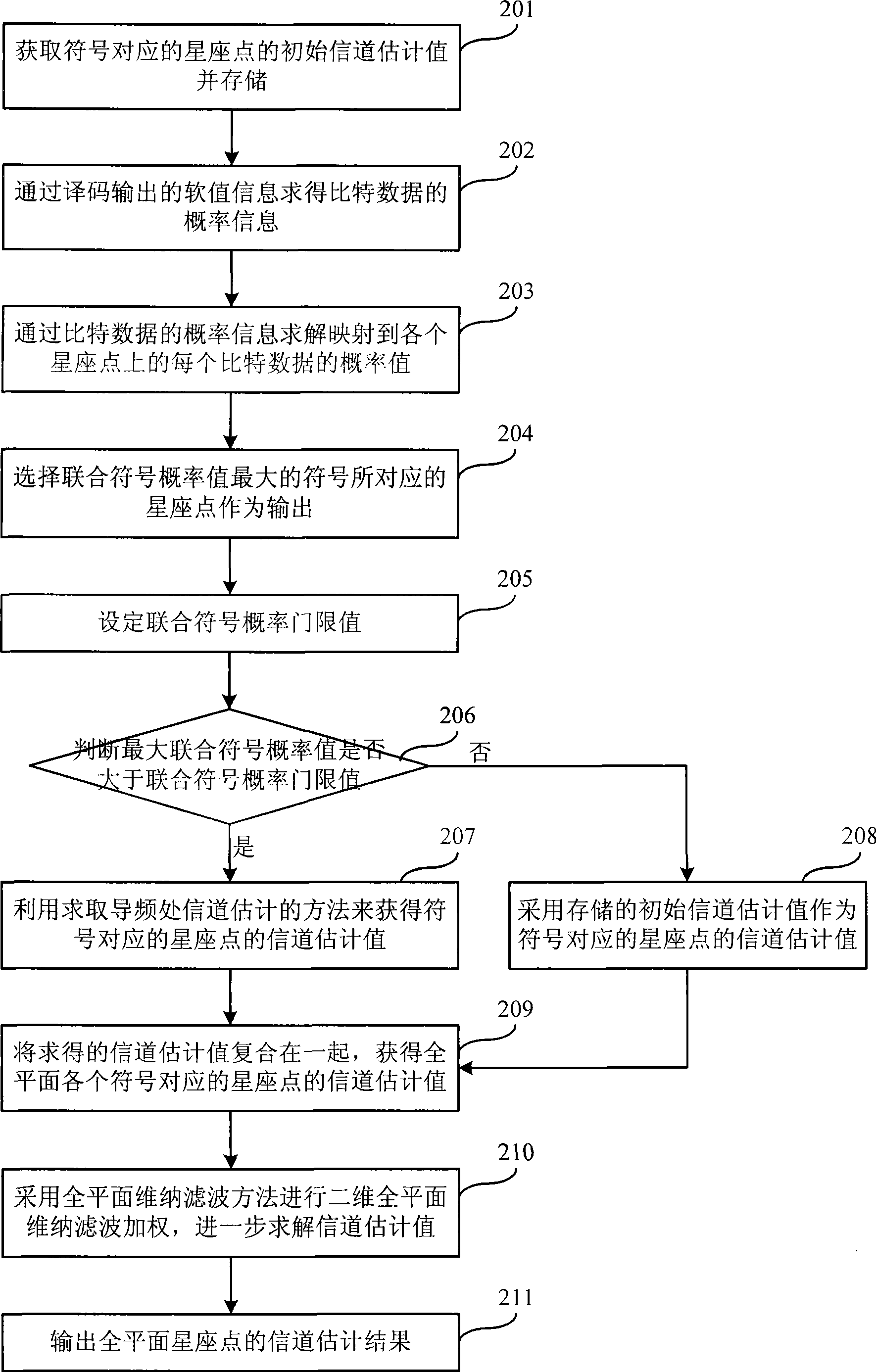
[0037] The scheme of the embodiment of the present invention uses the comparison of the joint symbol probability value and the preset joint symbol probability threshold value to obtain the constellation point corresponding to the symbol, and then calculates the channel estimation value for this constellation point, reducing the complexity of iterative channel estimation On the basis of , the reliability of channel estimation can be further improved. The technical solutions of the embodiments of the present invention are described in detail below.

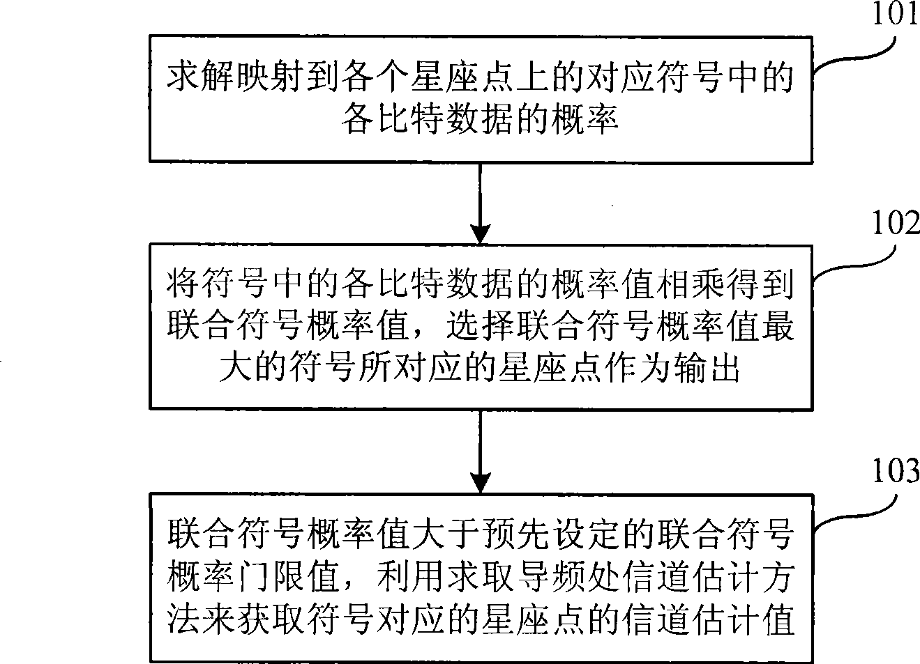
[0038] Such as figure 2 As shown, it is a schematic flow chart of Embodiment 1 of the channel estimation method of the present invention, which specifically includes the following steps:

[0039] Step 101, solving the probability of each bit of data in the corresponding symbol mapped to each constellation point;

[0040] In the background technology, we introduced the method of solving the probability of bit data, here we can use...


PUM


Abstract

The embodiment of the invention relates to a method for estimating a channel. The method comprises: the probability value of each bit data of a corresponding sign mapped to each constellation point is solved; the probability value of each bit data multiplies to obtain a joint sign probability value; the constellation point corresponding to a sign with the largest joint sign probability value is selected as output; and when the joint sign probability value is more than the preset joint sign probability threshold value, a method for estimating a channel by solving pilot frequency is utilized toobtain the channel estimated value of the constellation point corresponding to the sign. The embodiment of the invention also relates to a device for estimating the channel; the device comprises a demodulator and an encoder; and the device also comprises a first channel estimator for solving the channel estimated value of the constellation point corresponding to the sign. The method and the device for estimating the channel realize the reduction of complexity of iterative channel estimation operation and increase reliability of iterative channel estimation, thereby shortening performance difference between actual channel estimation and ideal channel estimation.

Description

technical field [0001] The present invention relates to the technical field of communication service transmission, in particular to a channel estimation method and device. Background technique [0002] With the development of network technology, the requirements for the transmission capability of wireless links and the transmission rate of signals are getting higher and higher in service transmission, so as to improve the reliability of the communication system. For example: In Worldwide Interoperability for Microwave Access (hereinafter referred to as: WiMAX) and Long Term Evolution (hereinafter referred to as: LTE) systems, the convolutional Turbo code encoding method is introduced, and the signal passes through the channel in the physical layer. Finally, the channel estimation can be used to compensate the influence of the fading channel on the useful signal as much as possible. There are many methods for channel estimation. In WIMAX and LTE systems, the time-frequency t...

Claims


Application Information

Patent Timeline
Patent Type & Authority Applications(China)
IPC IPC(8): H04B1/74H04L1/00
Inventor 王艳梅黄睿江长国刘华斌李航
Owner HUAWEI TECH CO LTD
Learn More