

Filtering, cleaning, drying three-in-one device
A three-in-one, equipment technology, applied in the fields of filtration and separation, fixed filter element filters, chemical instruments and methods, etc., can solve the problems of low efficiency, harm to the human body, and physical harm to operators, and achieve the effect of reducing labor intensity.
- Summary
- Abstract
- Description
- Claims
- Application Information
AI Technical Summary
Problems solved by technology
Method used
Image

Examples
Embodiment Construction
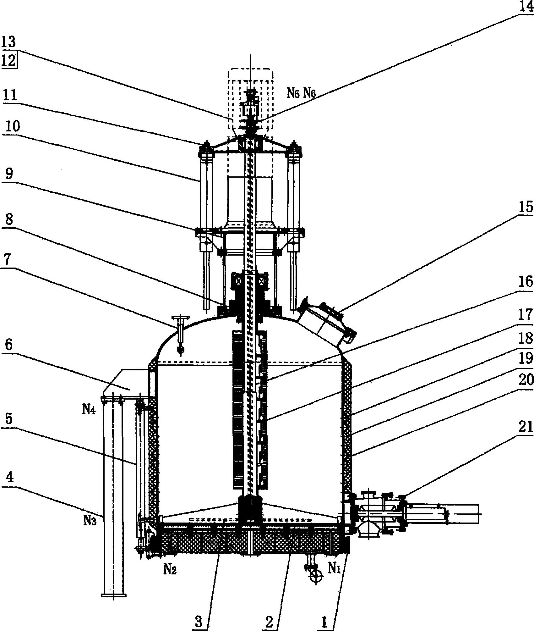
[0014] Such as figure 1 As shown, the filtration, washing and drying three-in-one equipment of the present invention consists of a chassis 1, tank body 18, legs 4, and support 6 to form a sealed and pressure-bearing cavity, which is convenient for materials on the tank body. Access and maintenance, manhole 15, cleaning ball 7 and other connecting pipe accessories are also installed, the outer wall of the tank body 18 and the outside of the chassis 1 are installed with an insulating layer 20, and a filter plate 2 is installed above the bottom chassis 1 of the tank body 18, which can be used The metal sintered plate, the chassis 1 and the tank body 18 are connected through the chassis lifting hydraulic cylinder 5, which is convenient for the replacement and cleaning of the filter disc 2; Shaft 16, bellows 17, frame 9, stirring and lifting hydraulic cylinder 10, and bracket 11. The stirring shaft 16 is sealed with the tank body through the mechanical seal 8. The explosion-proof m...
PUM
 Abstract
Description
Claims
Application Information