Winding-pipe production device

A technology of a winding device and a production device, which is applied in the direction of tubular articles, other household appliances, household appliances, etc., can solve the problems of high transportation cost of winding pipes, and achieve the effect of solving the high cost and flexible structure.

Inactive Publication Date: 2009-06-17
HUAHAN SCI & TECH
View PDF0 Cites 8 Cited by
  • Summary
  • Abstract
  • Description
  • Claims
  • Application Information

AI Technical Summary

Problems solved by technology

[0006] The technical problem to be solved by the present invention is to provide a winding pipe production device, which realizes the production of winding pipes at the site where the winding pipes are used, and solves the defect of high transportation cost of winding pipes

Method used


Image

  • Winding-pipe production device
  • Winding-pipe production device
  • Winding-pipe production device

Examples


Embodiment 1

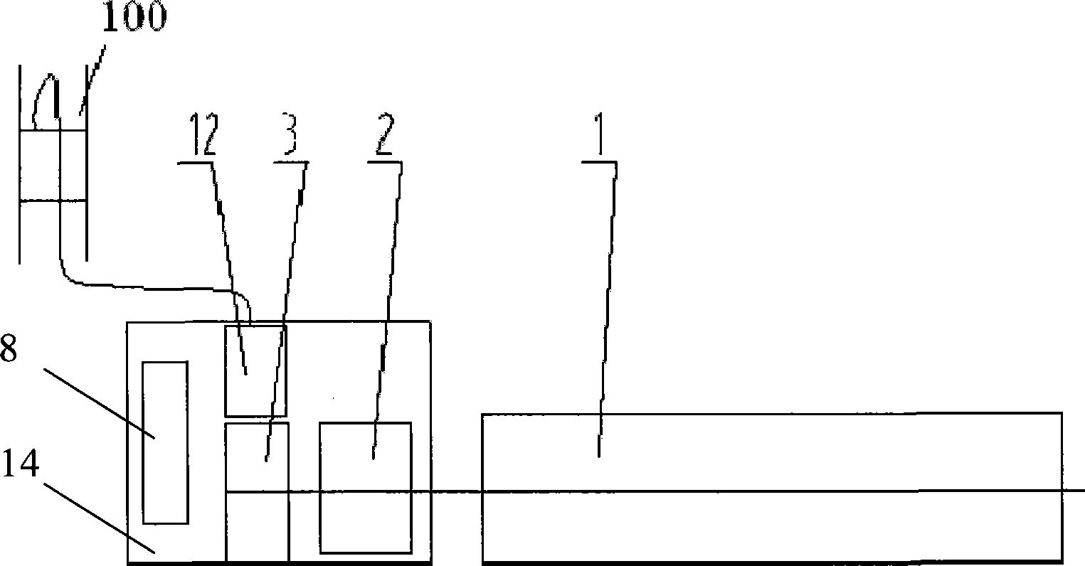
[0034] Such as image 3 As shown, in the present embodiment, the tape supply part includes an independent movable composite tape support 100 that cooperates with the feeding device, the feeding device is a tape feeding device 12, and the power supply end of the control system 8 is connected with the tape feeding device 12, winding The device 3 is connected with the driving mechanism of the pipe material cutting device 2 . The control system 8, the tape feeding device 12, the winding device 3 and the pipe material cutting device 2 are arranged on the same movable foundation 14, and the supporting frame 1 is arranged on another movable foundation (not shown in the figure).

Embodiment 2

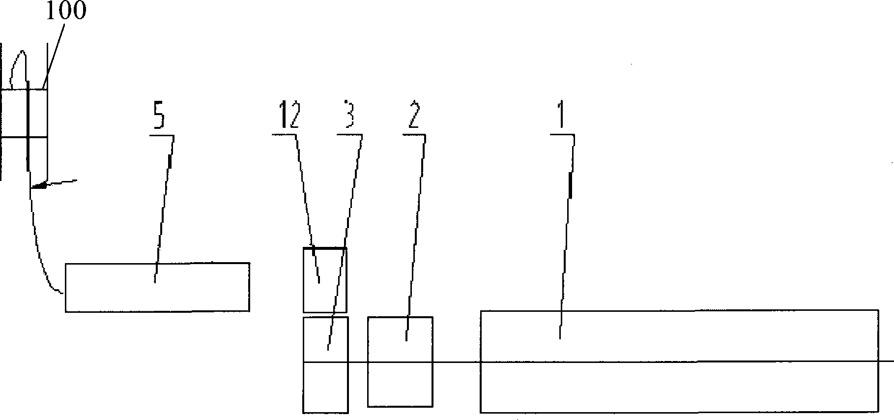
[0036] Such as Figure 4 As shown, the strip supply part in this embodiment includes a composite strip support 100 and a guide device 5 matched therewith. The discharge end of the guide device 5 is adjacent to the feed device 12, and the direction of its entry and exit is along the axis of the pipe production section. The direction (that is, the axial direction of the sequentially arranged winding device 3 , pipe material cutting device 2 and support frame 1 ) is set. The power supply end of the control system 8 is connected with the driving mechanism of the guiding device 5 , the feeding device 12 , the winding device 3 and the pipe cutting device 2 , and in this embodiment, the feeding device is the belt feeding device 12 . Control system 8, guiding device 5, belt feeding device 12, winding device 3 and pipe material cutting device 2 are arranged on the platform of special vehicle 11, and support frame 1 is arranged on another movable foundation (not shown in the figure).

Embodiment 3

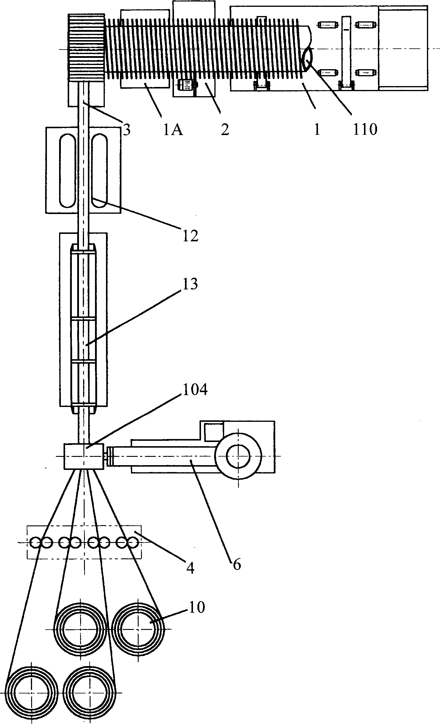
[0038] Such as Figure 5 As shown, in the present embodiment, the strip supply part includes a steel strip material preparation section, a guide device 5, a sealing and welding plastic extruder 61 and an independent movable pure plastic semi-finished strip support 101 that cooperates with the feed device, and the feed device The straightening device 4 is used to flatten the steel strip and integrate the steel strip and the pure plastic semi-finished strip into one. The discharge end of the guide device 5 is adjacent to the straightening device 4, and the direction of the in-out belt of the guide device 5 is set along the axial direction of the pipe production part (that is, the axial direction of the sequentially arranged winding device 3, pipe cutting device 2 and support frame 1), The power supply end of the control system 8 is connected with the driving mechanism of the guiding device 5, the straightening device 4, the winding device 3, the pipe material cutting device 2 an...


PUM


Abstract

The invention relates to a wound pipe production device. The production device comprises a belt supplying part, a pipe production part, a control system and a movable foundation, wherein the control system and the movable foundation are connected with a driving mechanism of the belt supplying part and the pipe production part. The pipe production part comprises a feeding device, a winding device, a pipe cutting device and a support, wherein the feeding device, the winding device, the pipe cutting device and the support are arranged on the movable foundation. The winding device, the pipe cutting device and the support are arranged sequentially in a matching mode. The feeding device and the winding device are arranged in a matching mode to realize feeding along a cutting direction. The wound pipe production device can be delivered to a site where pipes are used for on-site production, thereby saving pipe transpiration and pipe transportation cost. The wound pipe production device is flexible in structure, can use compound belts as raw material to product pipes, carry out complete belt production and pipe production, use steel strips and plastic raw materials to produce pipes and produce wound pipes of various pipe diameters.

Description

technical field [0001] The present invention relates to a pipe material production device, more specifically, to a coiled pipe production device. Background technique [0002] Steel-plastic composite winding pipe has been widely used for its excellent pipe body strength, high rigidity, light weight and other properties, and the production of winding pipe has also realized assembly line operation. Such as figure 1 Shown is a typical production line for winding pipes in the workshop, including two parts: strip production and pipe production. The strip production part includes that the steel strip passes through the feeding device 10 and is straightened by the straightening device 4, then enters the mold 104 to be compounded with the molten plastic extruded by the extruder 6, and then cools and shapes on the shaping table 13. The front of the platform 13 is provided with a belt feeding device 12 to pull the produced strip. The pipe production part includes a spiral winding d...

Claims


Application Information

Patent Timeline
Patent Type & Authority Applications(China)
IPC IPC(8): B29C69/00B29C31/08B29K705/12B29L23/00
Inventor 郑能欢董勉励
Owner HUAHAN SCI & TECH
Why Eureka
Try Eureka