
Laser processing apparatus, laser processing method, and method for making settings for laser processing apparatus

A laser processing and laser technology, applied in laser welding equipment, metal processing equipment, welding equipment and other directions, can solve problems such as crystal end face deformation and focal length change

Inactive Publication Date: 2009-06-17
KEYENCE
View PDF1 Cites 51 Cited by
  • Summary
  • Abstract
  • Description
  • Claims
  • Application Information

AI Technical Summary

Problems solved by technology

[0007] On the other hand, laser crystals will cause deformation of the crystal end faces due to heat. This phenomenon is called thermal lensing, and this phenomenon will cause the problem of focal length changes.

Method used


Image

  • Laser processing apparatus, laser processing method, and method for making settings for laser processing apparatus
  • Laser processing apparatus, laser processing method, and method for making settings for laser processing apparatus
  • Laser processing apparatus, laser processing method, and method for making settings for laser processing apparatus

Examples


Embodiment Construction

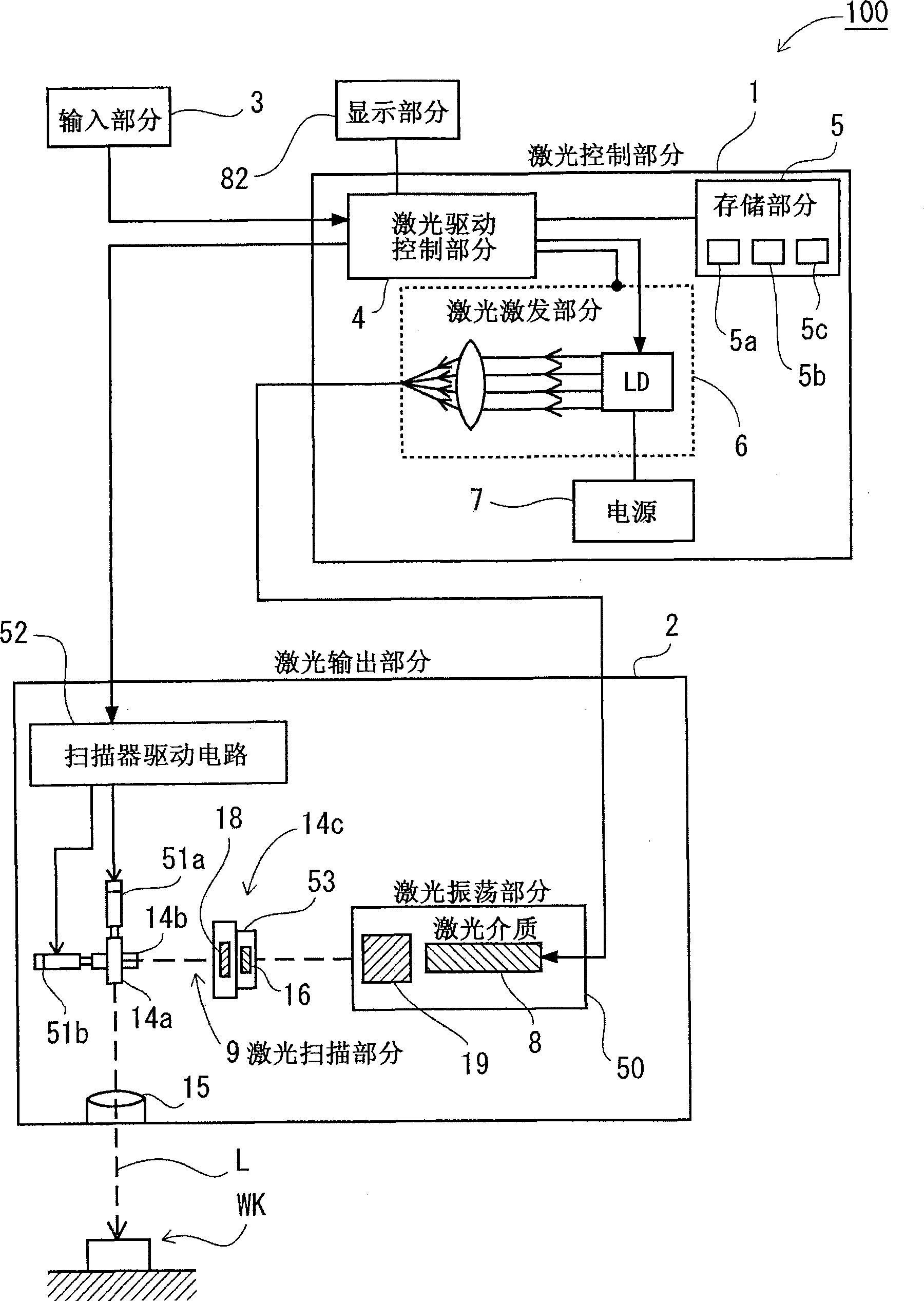
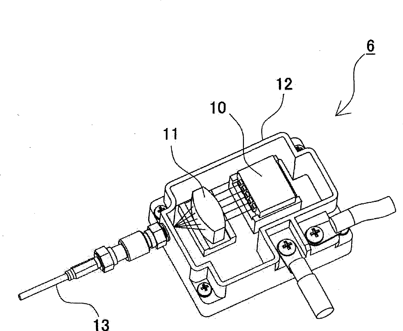
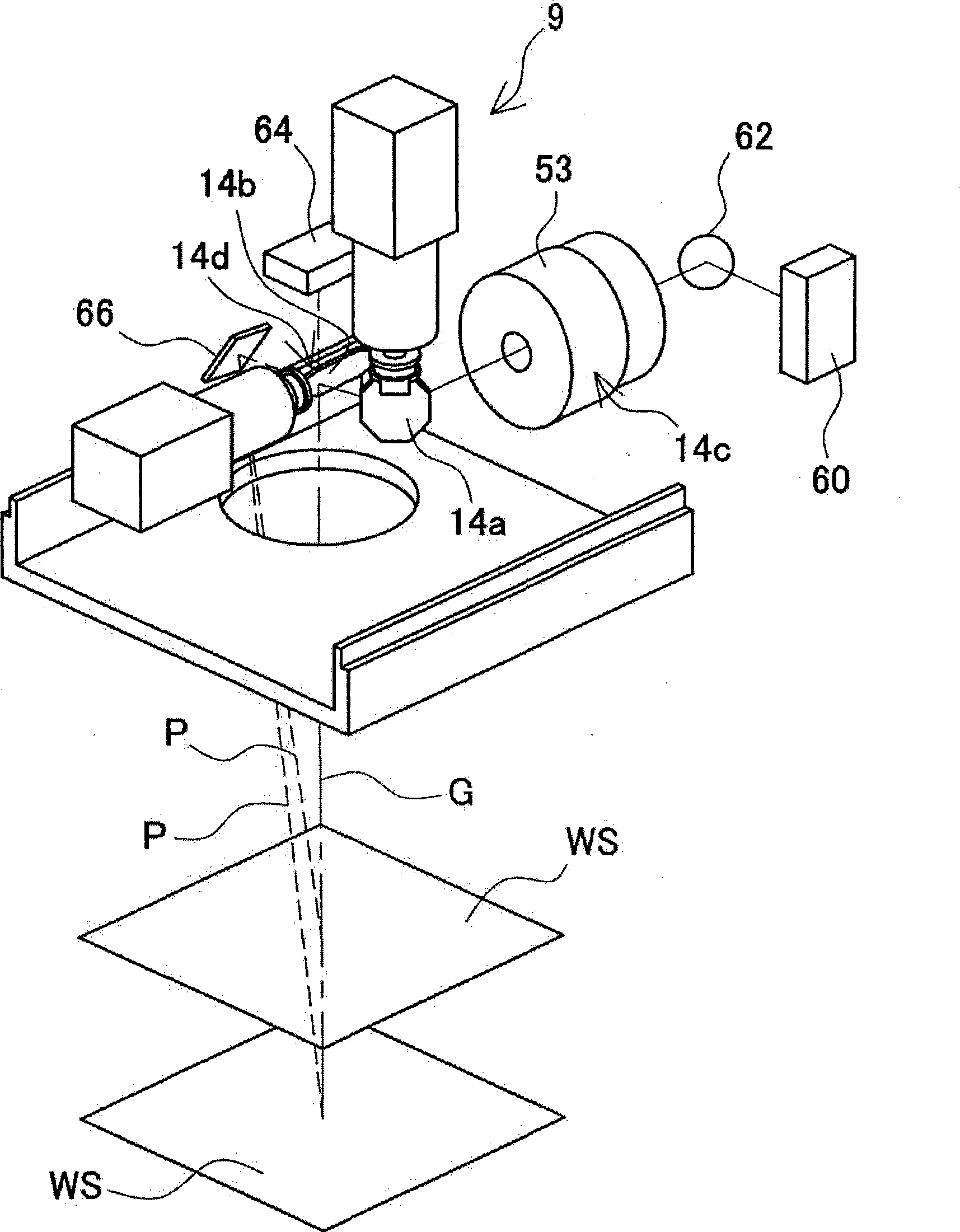
[0057] Embodiments of the present invention will be described below with reference to the accompanying drawings. In the embodiments to be described below, the laser processing equipment, the laser processing method and the method for setting the laser processing equipment embodying the technical concept of the present invention will be illustrated, and in the present invention, the laser processing equipment, the laser processing method and the The method for setting up the laser processing equipment is not limited to the specific way that will be described below. Also, in this specification, the elements defined in the claims are by no means limited to the elements in the embodiment. In particular, unless otherwise stated, the dimensions, materials, shapes and relative orientations of components to be described in the implementation are illustrative only and not meant to limit the scope of the present invention. Also, the size of elements and the positional relationship betw...


PUM


Abstract

It is an object to enable easily adjusting a focus position for coping with thermal lens effects. There is provided a laser-light scanning portion including a Z-axis scanner capable of adjusting the focus position of laser light in the direction of the optical axis, an X-axis scanner and a Y-axis scanner. Further, there are provided a laser driving control portion for controlling a laser oscillation portion and the laser-light scanning portion, a processing-condition setting portion for setting a laser-light outputting condition and a processing pattern as processing conditions for processing in a desired processing pattern, and an amount-of-correction identification section for identifying, as an amount of focus-position correction, the deviation of the focus position in the direction of the optical axis which is caused by thermal lens effects induced based on the laser-light outputting condition set by the processing-condition setting portion. During irradiation of the laser light, the laser driving control portion scans the laser light, in such a way as to add the amount of focus-position correction identified by the amount-of-correction identification section to the processing condition set by the processing-condition setting portion.

Description

[0001] Cross References to Related Applications [0002] This application claims foreign priority based on Japanese Patent Application No. 2007-323686 filed on December 14, 2007, the contents of which are incorporated herein by reference. technical field [0003] The present invention relates to a laser processing device, such as a laser marking device, for guiding laser light onto an object to be processed for processing such as printing, and to a laser processing method and a method for processing laser The method of setting up the processing equipment. Background technique [0004] The laser processing apparatus is adapted to scan laser light over a predetermined area for directing the laser light onto the surface of an object to be processed (workpiece) such as components and products to perform processing such as printing and marking thereon. Figure 22 An exemplary structure of a laser processing apparatus is illustrated. The laser processing apparatus shown in this f...

Claims


Application Information

Patent Timeline
Patent Type & Authority Applications(China)
IPC IPC(8): B41J2/47B23K26/00G02B26/10B23K26/046B23K26/082
CPCB23K26/0807B41J2/471G02B26/12B23K26/082
Inventor 佐藤雅夫山川英树
Owner KEYENCE
Learn More