Charge depleting energy management strategy for plug-in hybrid electric vehicles

A hybrid electric vehicle, plug-in technology, applied in electric vehicle charging technology, hybrid electric vehicles, motor vehicles, etc., can solve problems such as reducing engine fuel economy

Active Publication Date: 2009-06-17
FORD GLOBAL TECH LLC
View PDF1 Cites 7 Cited by
  • Summary
  • Abstract
  • Description
  • Claims
  • Application Information

AI Technical Summary

Problems solved by technology

However, this is not the case because, when electrical power is converted to mechanical power and mechanical power is converted to electrical p

Method used


Image

  • Charge depleting energy management strategy for plug-in hybrid electric vehicles
  • Charge depleting energy management strategy for plug-in hybrid electric vehicles
  • Charge depleting energy management strategy for plug-in hybrid electric vehicles

Examples


Embodiment Construction

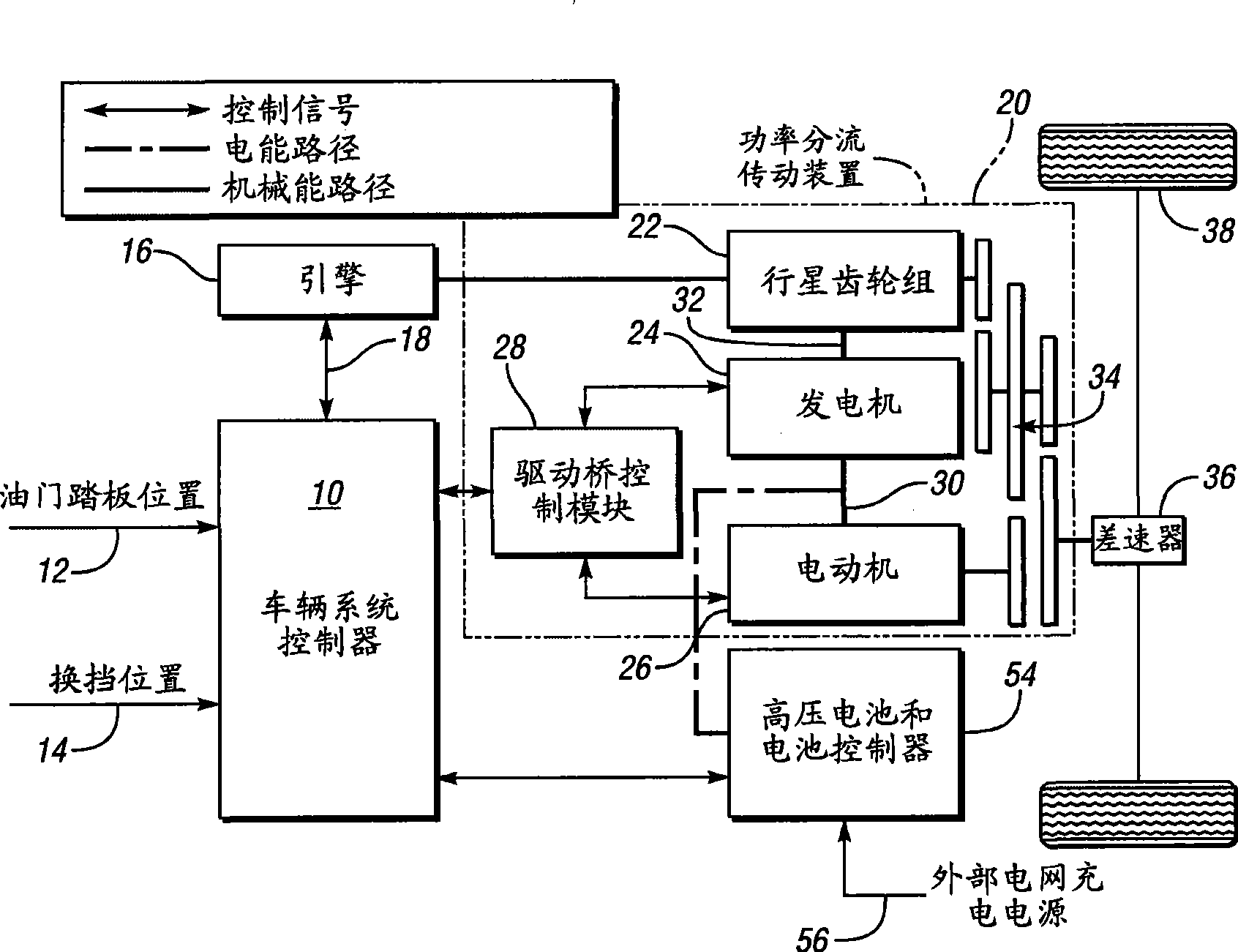
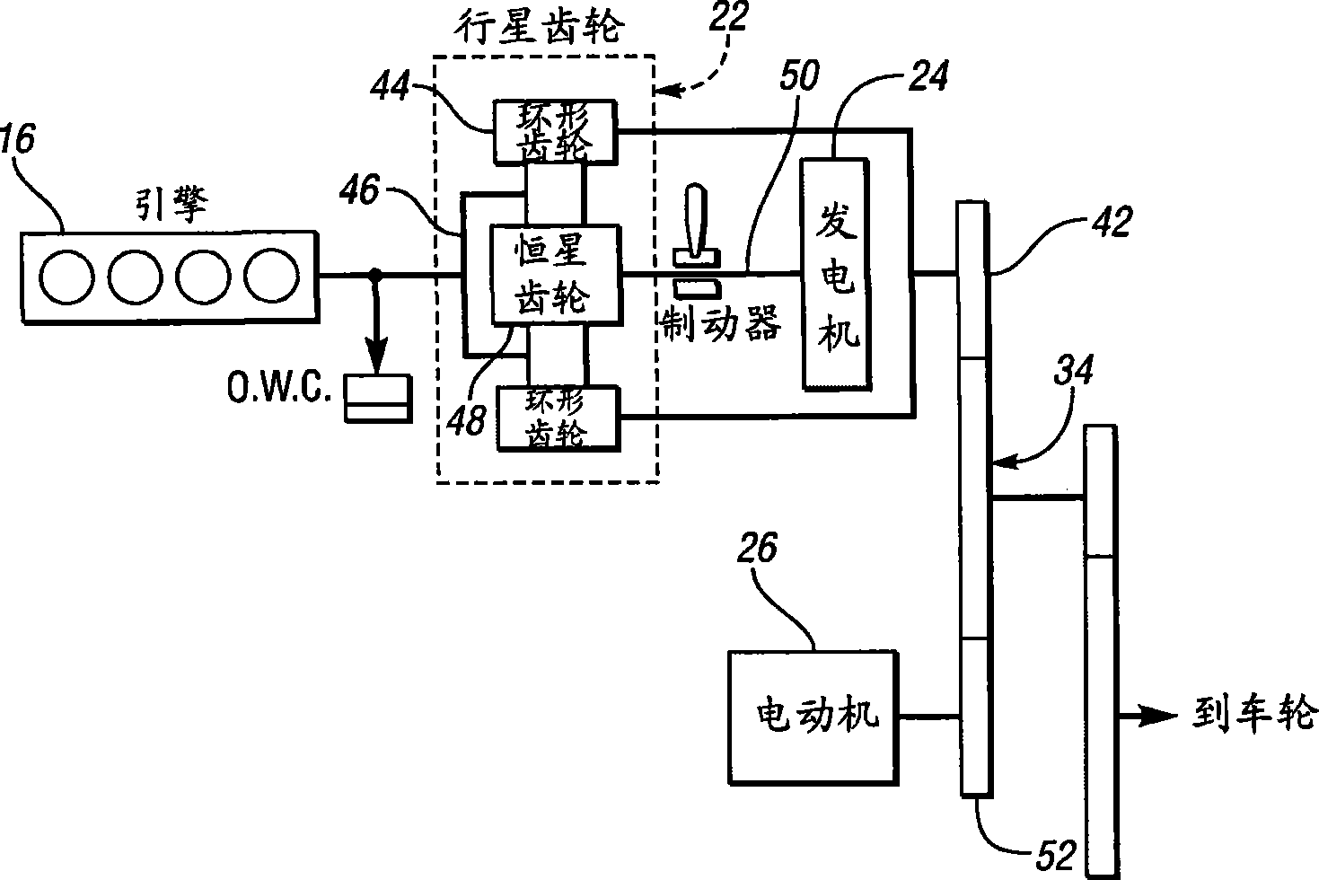
[0018] figure 1 and Figure 1a The powertrain configuration is the power-split hybrid electric vehicle powertrain, which is one example in the class of hybrid electric vehicle powertrains known as parallel hybrid electric vehicles. Although it will be described in detail figure 1 and Figure 1a The strategy of the present invention can also be applied to other hybrid configurations. For example, it can also be applied to hybrid powertrains with a single motor / generator.

[0019] exist figure 1 Among them, the vehicle system controller 10 receives signals input by the driver of the vehicle, and the signals input by the driver of the vehicle include an accelerator pedal position signal 12 and a gear selection signal 14 . The engine 16 communicates engine speed and engine torque signals to the vehicle system controller, shown at 18 . The engine transmits power to a power split transmission 20 which includes a planetary gear set 22 , a generator 24 and an electric motor 26 ....


PUM


Abstract

A method for managing power distribution from an engine and a battery in a plug-in hybrid electric vehicle whereby battery power is used to meet a driver demand for power and engine power complements battery power when either battery state-of-charge limit or battery discharge power limit would be exceeded, an external power grid being used to restore battery power following battery charge depletion.

Description

technical field [0001] The invention relates to a hybrid electric vehicle having a traction motor, an engine and a traction battery, wherein the traction battery can be charged by using an external power grid. Background technique [0002] A known hybrid electric vehicle powertrain may have an engine, a generator, where the energy source for the engine is hydrocarbon-based fuel, and an electric motor, where the energy source for the electric motor is a high voltage battery and generator subsystem. The battery can be charged by the engine using fuel stored in the vehicle or from an external grid. In the case of hybrid electric vehicles where the battery is charged from an external grid, an all-electric vehicle range is possible while the engine is switched off, thereby avoiding undesired engine exhaust emissions. This feature is especially important for vehicles operating in urban environments. Such vehicles, sometimes referred to as plug-in hybrid electric vehicles, are al...

Claims


Application Information

Patent Timeline
IPC IPC(8): B60W10/26B60W10/06B60W20/00
CPCB60W20/00Y02T90/14B60W30/188Y02T10/6269Y10S903/93Y02T10/62B60K2006/268B60W20/13B60W10/26
Inventor 大窪俊介邝明朗大卫·瑞奇斯·伯瑞翰迈克尔·艾伦·塔摩
Owner FORD GLOBAL TECH LLC
Why Eureka
Try Eureka