Bridge erection method

A technology for bridges and beam sections, which is applied in the field of bridge erection in narrow construction sites, can solve the problems of narrow and uneven construction sites, inconvenient transportation, and inability to use large lifting equipment.

Active Publication Date: 2009-06-17
THE SECOND OF CHINA RAILWAY PORT CHANNEL ENG GROUP +1
View PDF0 Cites 20 Cited by
  • Summary
  • Abstract
  • Description
  • Claims
  • Application Information

AI Technical Summary

Problems solved by technology

This is not suitable for projects with narrow and uneven construction sites, inconvenient transportation, projects that cannot use large-scale lifting equipment, or projects that do not have large-scale lifting equipment.

Method used


Image

  • Bridge erection method
  • Bridge erection method
  • Bridge erection method

Examples


Embodiment

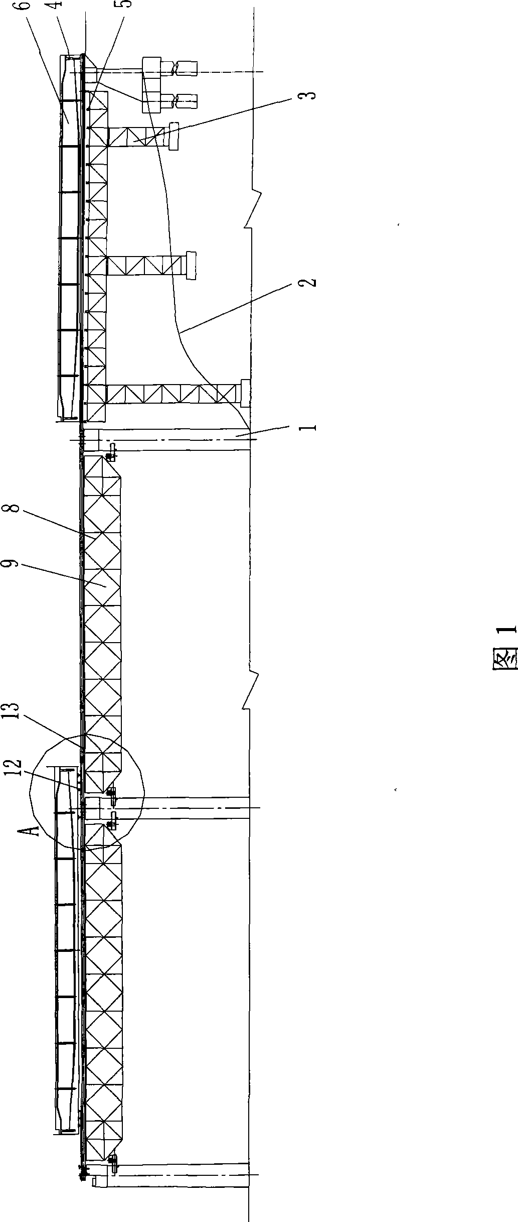
[0024] As shown in Figure 1, a bridge erection method, after each pier is built at the design position, the bridge erection is carried out according to the following steps:

[0025] A. Process the slope surface 2 on the side of each bridge pier 1; install the beam section prefabricated support 3 between the two adjacent bridge piers of the side holes; 6 precast;

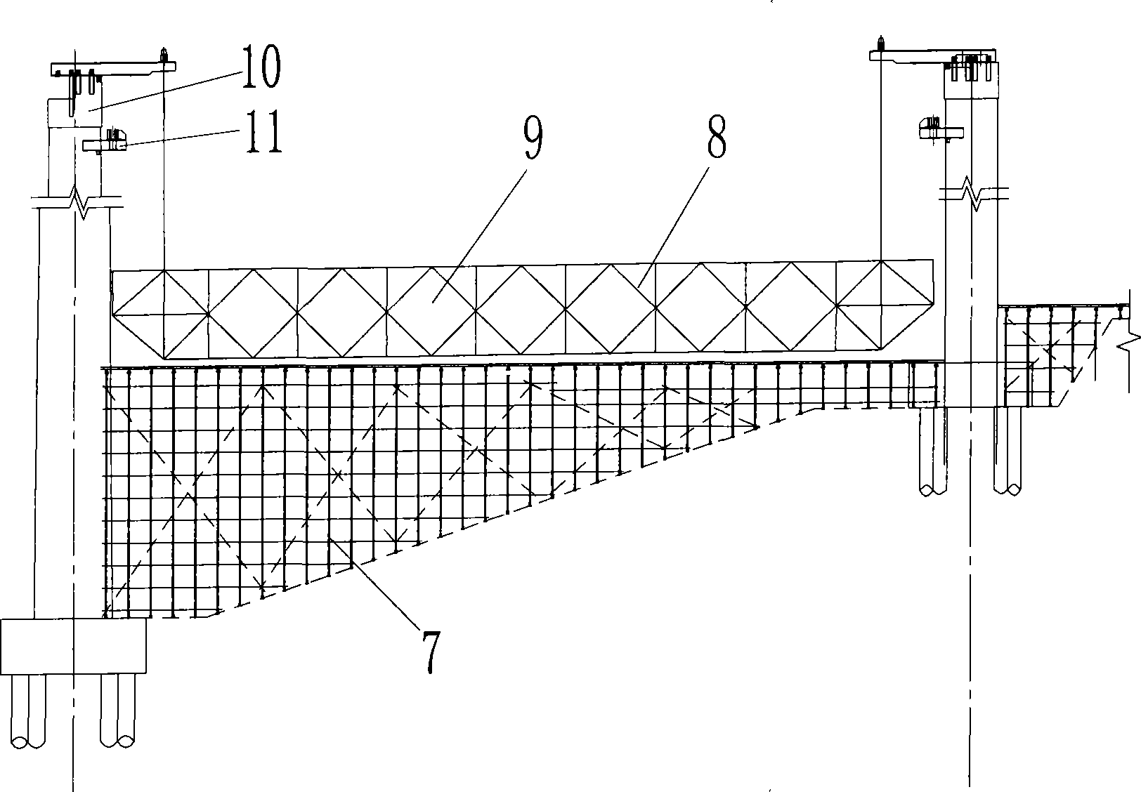
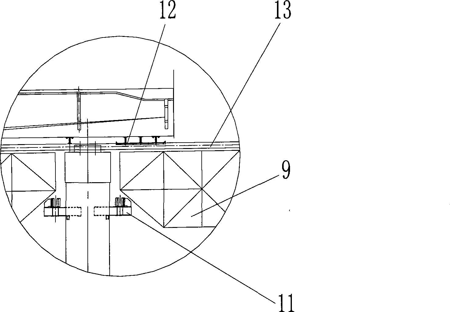
[0026] B. If figure 2 As shown, steel pipe scaffolding 7 is set up between every other adjacent two bridge piers; guide beams 9 are assembled with universal rods 8 on each steel pipe scaffolding 7; Lift to the design position and install between two adjacent piers 1, the two ends of the guide beam 9 are fixed on the cap beam embedded parts 11 of the piers;

[0027] C. Install the slideway 13 for the longitudinal sliding of the tackle 12 on the guide beam 9, install the slideway 13 for the transverse sliding of the tackle 12 on the pier top, and install a jack and a traction cable on the front end pier item;

[002...


PUM


Abstract

The invention discloses a bridge building method. After piers are built at the designed positions, beam segment prefabrication brackets are arranged between two piers having adjacent side holes and then the beam segments are prefabricated; guide beams are built between each other two adjacent piers; and the prefabricated beam segments are respectively built at the transverse and longitudinal designed positions by the coordination of pulleys and slide rails as well as the traction of jacks and traction cables. The invention breaks the limit of the construction site, and solves the prefabricated beam segment construction problem that the large-scale equipment can not be used in places with narrow site and inconvenient transport.

Description

technical field [0001] The invention relates to bridge erection technology, in particular to a bridge erection method for narrow construction sites such as hillsides. Background technique [0002] There are generally two sources of bridge prefabricated beam sections: one is on-site prefabrication, which requires a larger and flatter site for the prefabricated beam field; the other is to purchase finished beams directly from the factory, which requires convenient transportation The transportation route mainly refers to smooth railway transportation. Moreover, whether it is prefabricated on site or purchased from a factory, large lifting equipment is required to hoist the prefabricated beam sections in place during erection. This is not suitable for projects with narrow and uneven construction sites, inconvenient transportation, projects that cannot use large-scale lifting equipment, or projects that do not have large-scale lifting equipment. Contents of the invention [0...

Claims


Application Information

Patent Timeline
Patent Type & Authority Applications(China)
IPC IPC(8): E01D21/00E01D21/06
Inventor 王雄飞廖云沼孙迎春王艳青叶李
Owner THE SECOND OF CHINA RAILWAY PORT CHANNEL ENG GROUP
Why Eureka
Try Eureka