Vertical axis magnetic floating wind power generator

A wind turbine, vertical axis technology, applied in wind turbines, wind turbine combinations, wind turbines at right angles to the wind direction, etc., can solve the problems of limited wind power, inability to fully and effectively use wind power, and general products without structure. , to achieve the effect of smooth rotation

Inactive Publication Date: 2009-06-17
叶恩综
View PDF0 Cites 6 Cited by
  • Summary
  • Abstract
  • Description
  • Claims
  • Application Information

AI Technical Summary

Problems solved by technology

[0004] Although this existing wind power tower can drive the generator set to generate electricity through the wind force, its arc-shaped blade 11 can only utilize the wind force blowing to its concave surface 111, while other wind forces blowing to the convex surface 112 of the blade 11, Not only does it fail to form an effective thrust on the rotating tower, but because of the concave surface 111 opposite to the blade 11, it forms resistance to the rotation of the rotating tower 10, resulting in limited available wind power, and cannot fully and effectively utilize all the wind power. Generates electricity, very not ideal
[0005] This shows that the above-mentioned existing rotary wind power tower obviously still has inconvenience and defects in structure and use, and needs to be further improved urgently
In order to solve the above-mentioned problems, the relevant manufacturers have tried their best to find a solution, but no suitable design has been developed for a long time, and the general products do not have a suitable structure to solve the above-mentioned problems. This is obviously related. The problem that the industry is eager to solve

Method used


Image

  • Vertical axis magnetic floating wind power generator
  • Vertical axis magnetic floating wind power generator
  • Vertical axis magnetic floating wind power generator

Examples


Embodiment Construction

[0065] In order to further explain the technical means and effects that the present invention adopts to achieve the intended purpose of the invention, the specific implementation, structure, characteristics and details of the vertical axis maglev wind generator proposed according to the present invention will be described below in conjunction with the accompanying drawings and preferred embodiments. Its effect is described in detail below.

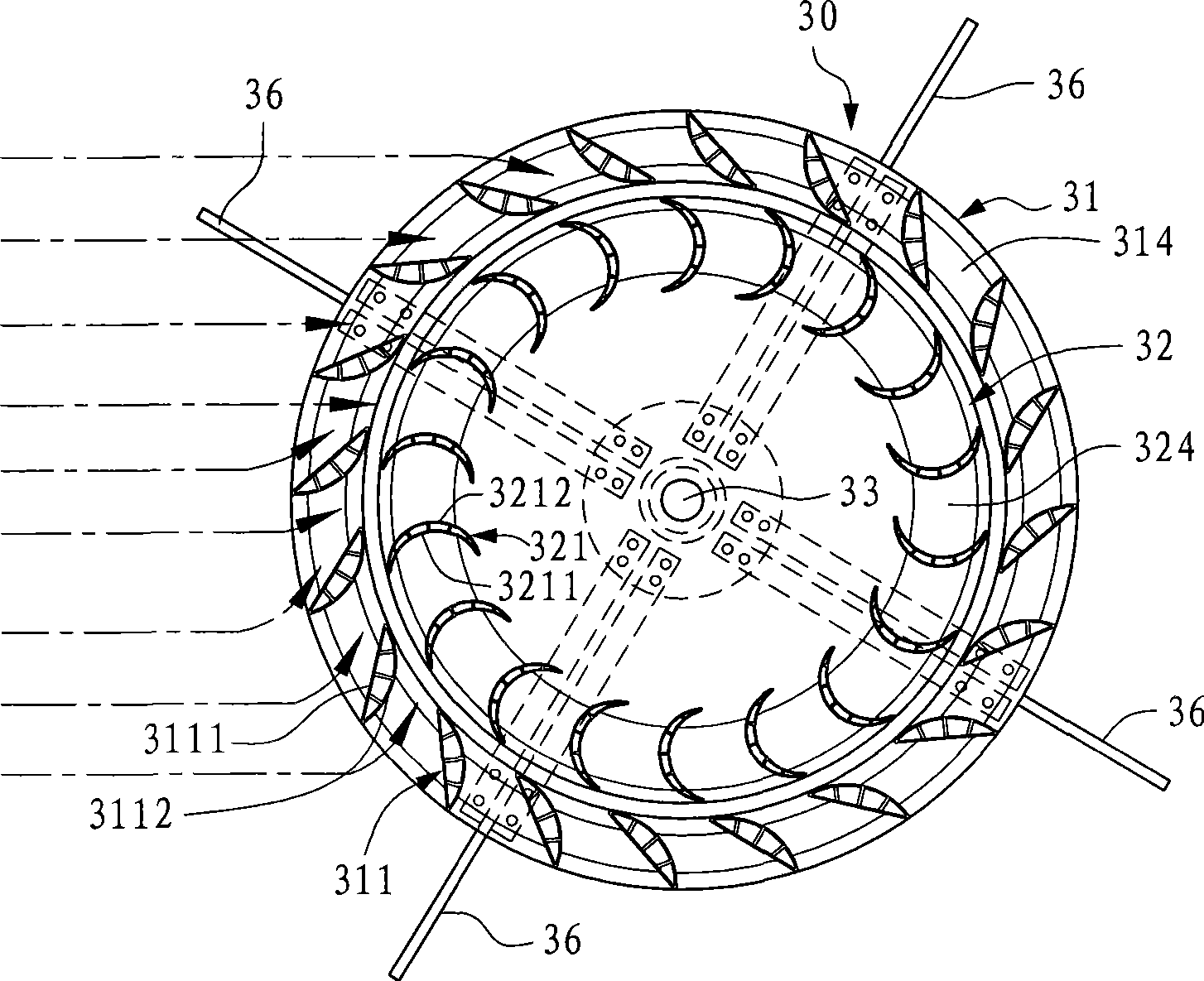
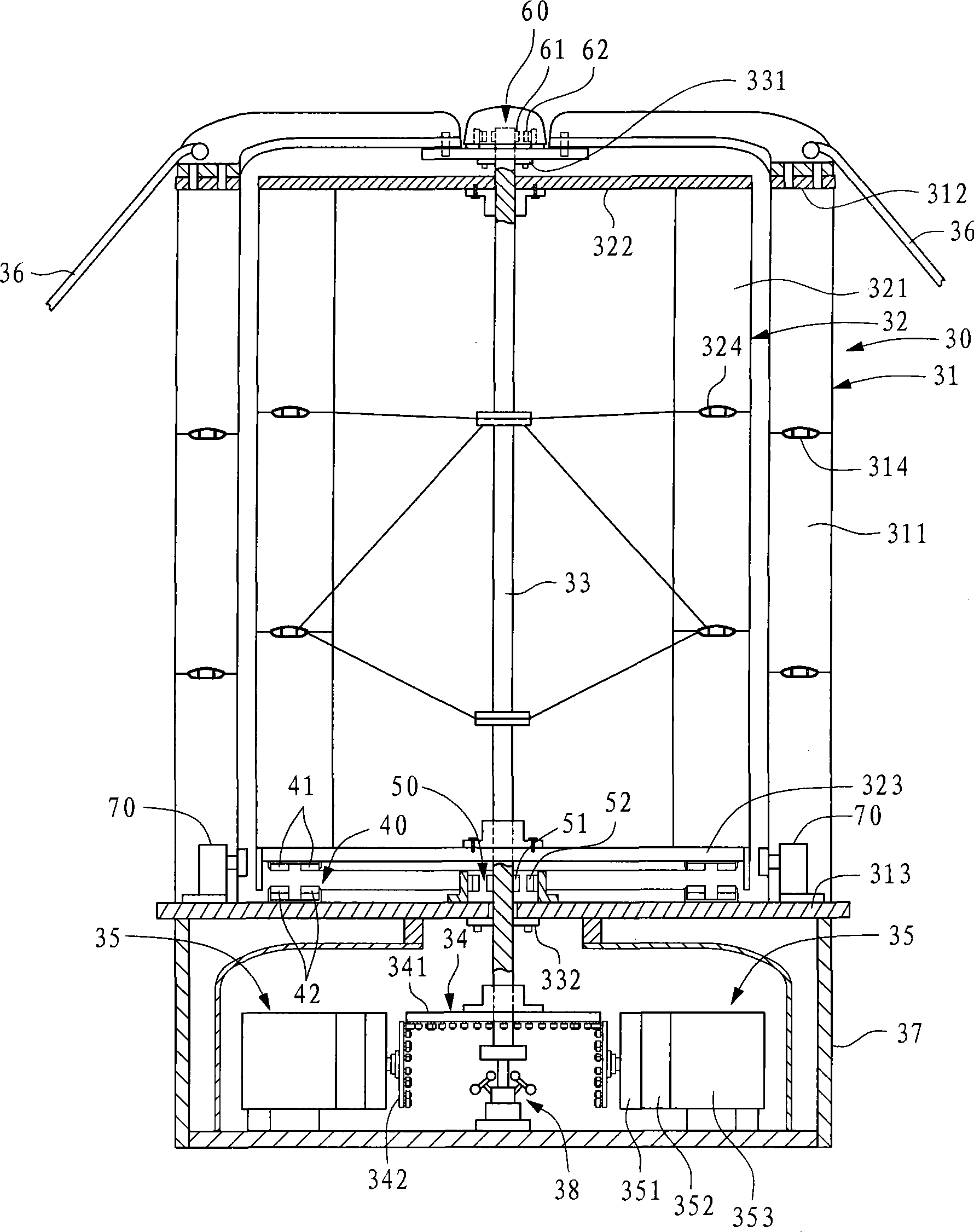
[0066] figure 2 , image 3 A schematic longitudinal section of a preferred embodiment of the structure of the vertical axis maglev wind power generator of the present invention and a schematic cross section of the rotary wind power tower are shown respectively. As shown in these figures, the wind power generator of the present invention is provided with a rotating wind tower 30 , and the rotating wind tower 30 includes a fixed outer tower 31 and a rotating inner tower 32 . The upper and lower ends of the fixed outer tower 31 are respect...


PUM


Abstract

The invention relates to a magnetic suspension aerogenerator with a vertical shaft. The magnetic suspension aerogenerator is provided with a rotary wind-force tower, wherein, the wind-force tower comprises a fixed outer tower and a rotary inner tower; the periphery of the fixed outer tower is vertically wound by a plurality of flow deflectors which are provided with wind-guiding planes and wind-guiding cambered surfaces and can guide the wind force into the rotary inner tower; the rotary inner tower is pivoted in the center of the fixed outer tower by a rotating shaft, the periphery of the rotary inner tower is vertically wound by a plurality of vanes facing towards the flow deflectors, and the rotating shaft in the rotary inner tower is connected with a plurality of electric generator groups by transmission equipment so as to drive the electric generator groups to generate power. A magnetic suspension device is arranged between the rotary inner tower and the fixed outer tower, and an electric generator controller is installed at the bottom end of the rotating shaft and can control the start or the close of equivalent amount of electric generator groups according to the degree of wind force.

Description

technical field [0001] The invention relates to a vertical axis maglev wind power generator, in particular to a wind power generator which utilizes deflectors to reduce wind power loss, and uses a generator control device to control the starting of equal numbers of generator sets according to the magnitude of wind power. Background technique [0002] The wind force in nature is naturally formed, non-directional and unpredictable. If you want to use the wind force, you must effectively guide the wind force and wind direction. [0003] see figure 1 As shown, the general traditional rotary wind power tower is provided with a rotary tower 10, and the periphery of the rotary tower 10 is provided with a plurality of blades 11, and these blades 11 are arranged in the same direction and arranged at equal intervals on the periphery of the rotary tower 10, The section of each blade 11 is arc-shaped, and has a concave surface 111 for receiving and utilizing the wind force. The opposit...

Claims


Application Information

Patent Timeline
Patent Type & Authority Applications(China)
IPC IPC(8): F03D9/00F03D7/06F03D3/04F03D3/00F16C32/04F03D9/25
CPCF16C2300/34F16C2360/31Y02E10/72F16C39/066
Inventor 叶恩综
Owner 叶恩综
Why Eureka
Try Eureka