Improved upper cover oil separating structure for compressor

A separate structure and compressor technology, which is applied in the field of compressors, can solve the problems of affecting the heat transfer performance of air conditioners, reducing the service life of compressors, and aggravating pump body wear, so as to reduce the chance of pump body wear and motor burnout, reduce Effect of oil discharge rate and improvement of heat transfer performance

Inactive Publication Date: 2009-06-17
LG ELECTRONICS (TIANJIN) APPLIANCES CO LTD
View PDF0 Cites 5 Cited by
  • Summary
  • Abstract
  • Description
  • Claims
  • Application Information

AI Technical Summary

Problems solved by technology

When the compressor is running to compress the refrigerant of the air conditioner, the refrigerant in the circulation system of the air conditioner will carry the lubricating oil in the compressor through the exhaust pipe 2 and enter the circulation pipeline of the air conditioner. The inner wall of the compressor is smooth and cannot retain the lubricating oil carried in the refrigerant, which will gradually reduce the lubricating oil in the compressor, which will increase the wear of the pump body and the probability of motor burnout, resulting in a reduction in the service life of the compressor. After the oil refrigerant enters the circulation pipeline of the air conditioner, it will also affect the heat exchange performance of the air conditioner

Method used


Image

  • Improved upper cover oil separating structure for compressor
  • Improved upper cover oil separating structure for compressor
  • Improved upper cover oil separating structure for compressor

Examples


Embodiment Construction

[0028] The improved compressor upper cover oil separation structure provided by the present invention will be described in detail below in conjunction with the accompanying drawings and specific embodiments.

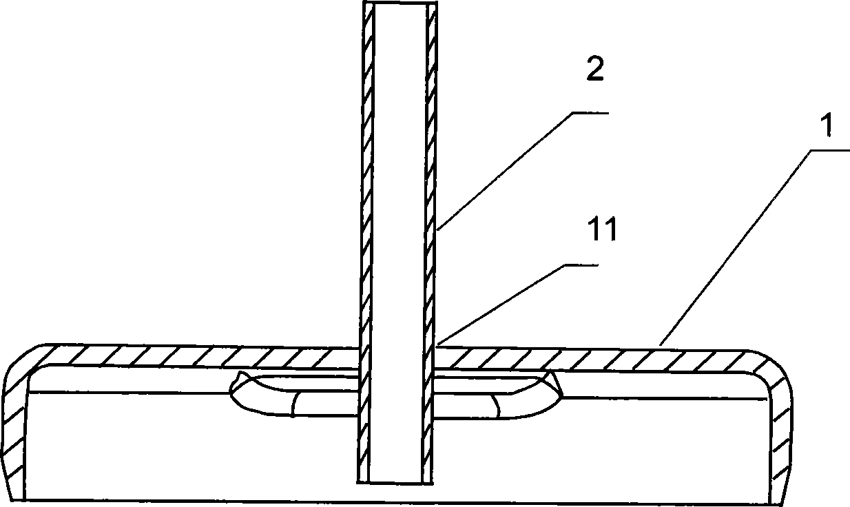
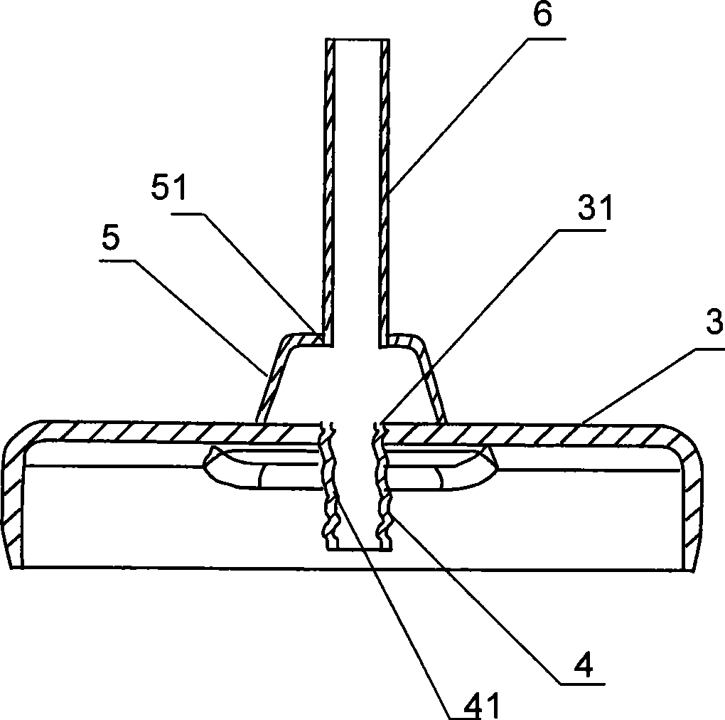
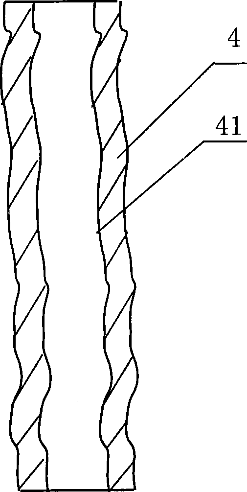
[0029] refer to figure 2 , image 3 As shown, the improved oil separation structure of the compressor upper cover of the present invention includes a compressor upper cover 3 and an exhaust pipe, and the top of the upper cover 3 is provided with an exhaust hole 31; the exhaust pipe is arranged as an upper exhaust pipe 6 and a lower exhaust pipe. Pipe 4, one end of the lower exhaust pipe 4 is connected with the exhaust hole 31 by the inner wall surface of the top cover 3 of the compressor, and the other end communicates with the inside of the compressor, and the lower exhaust pipe 4 is provided with a non-smooth inner wall surface 41; an oil The separator 5 is arranged at the outer edge of the exhaust hole on the top outer wall of the compressor upper cover 3 , and the ...


PUM


Abstract

The invention provides an improved upper cover oil separation structure for a compressor, comprising an upper cover of the compressor and exhaust pipes, wherein, the top of the upper cover is provided with an exhaust hole. The structure is characterized in that the exhaust pipes comprise an upper exhaust pipe and a lower exhaust pipe, wherein, one end of the lower exhaust pipe is connected with the exhaust hole by the inner wall surface of the top of the upper cover, the other end is communicated with the interior of the compressor, and the lower exhaust pipe is provided with an unflatness inner wall surface; an oil separator is arranged on the outer edge of the outer wall surface of the top of the upper cover of the compressor, and the top of the oil separator is communicated with the upper exhaust pipe; when cooling media carrying lubricating oil passes through the exhaust pipes, the action of the lower exhaust pipe of the unflatness inner wall surface and the oil separator causes the lubricating oil in the cooling media to be separated to be returned into the compressor, thereby realizing the effects of effectively reducing the oil output of the compressor, prolonging the service life of the compressor, improving the heat exchange performance of an air conditioner and saving the running cost of the air conditioner.

Description

1. Technical field [0001] The present invention relates to a compressor, in particular to an improved oil separation structure used for the upper cover of a compressor used in an air conditioner, which can effectively reduce the oil output of the compressor, thereby improving the heat exchange performance of the air conditioner and the service life of the compressor. The improved compressor upper cover oil separation structure saves the operating cost of the air conditioner. 2. Background technology [0002] A compressor is a mechanical device that can compress driving fluids such as air and refrigerant after receiving power transmitted by a power generating device such as a motor (motor) or a turbine (turbine), so that the pressure of the driving fluid raised. Such compressors are used in a wide variety of products ranging from general home appliances such as air conditioners and refrigerators to factory equipment. [0003] The above-mentioned compressors can be classifie...

Claims


Application Information

Patent Timeline
Patent Type & Authority Applications(China)
IPC IPC(8): F04C29/02
Inventor 崔静
Owner LG ELECTRONICS (TIANJIN) APPLIANCES CO LTD
Why Eureka
Try Eureka