Core rotor assembly dimension measuring device for turbo-charger

A turbocharger and rotor assembly technology, which is applied in the direction of measuring devices, instruments, etc., can solve the problems of unsuitable automatic assembly operations, high labor intensity of workers, and low measurement accuracy, so as to achieve easy query, strong versatility, and high measurement accuracy high effect

Inactive Publication Date: 2009-06-17
HARBIN INST OF TECH
View PDF0 Cites 15 Cited by
  • Summary
  • Abstract
  • Description
  • Claims
  • Application Information

AI Technical Summary

Problems solved by technology

[0003] The purpose of the present invention is to provide a turbocharger core rotor assembly size measurement device to solve the existing turbocharger core rotor assembly size measurement method that has cumbersome processes, high labor intensity, low measurement accuracy, and cannot be applied Problems with automated assembly operations

Method used


Image

  • Core rotor assembly dimension measuring device for turbo-charger
  • Core rotor assembly dimension measuring device for turbo-charger
  • Core rotor assembly dimension measuring device for turbo-charger

Examples


specific Embodiment approach 1

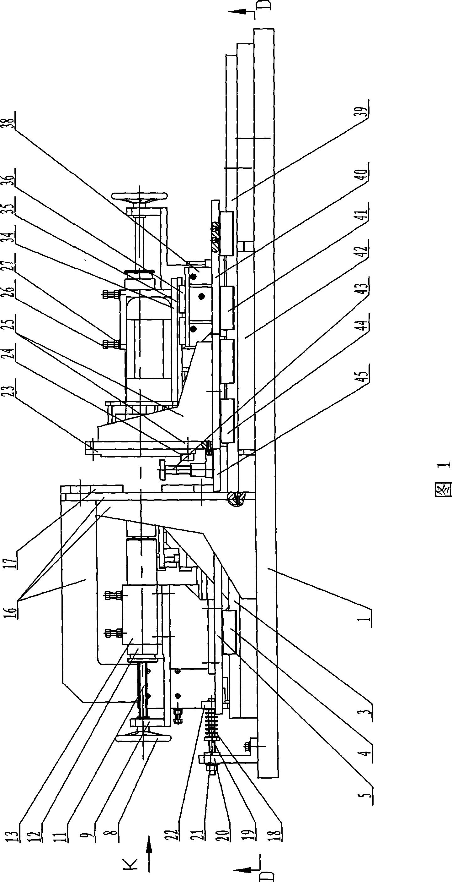
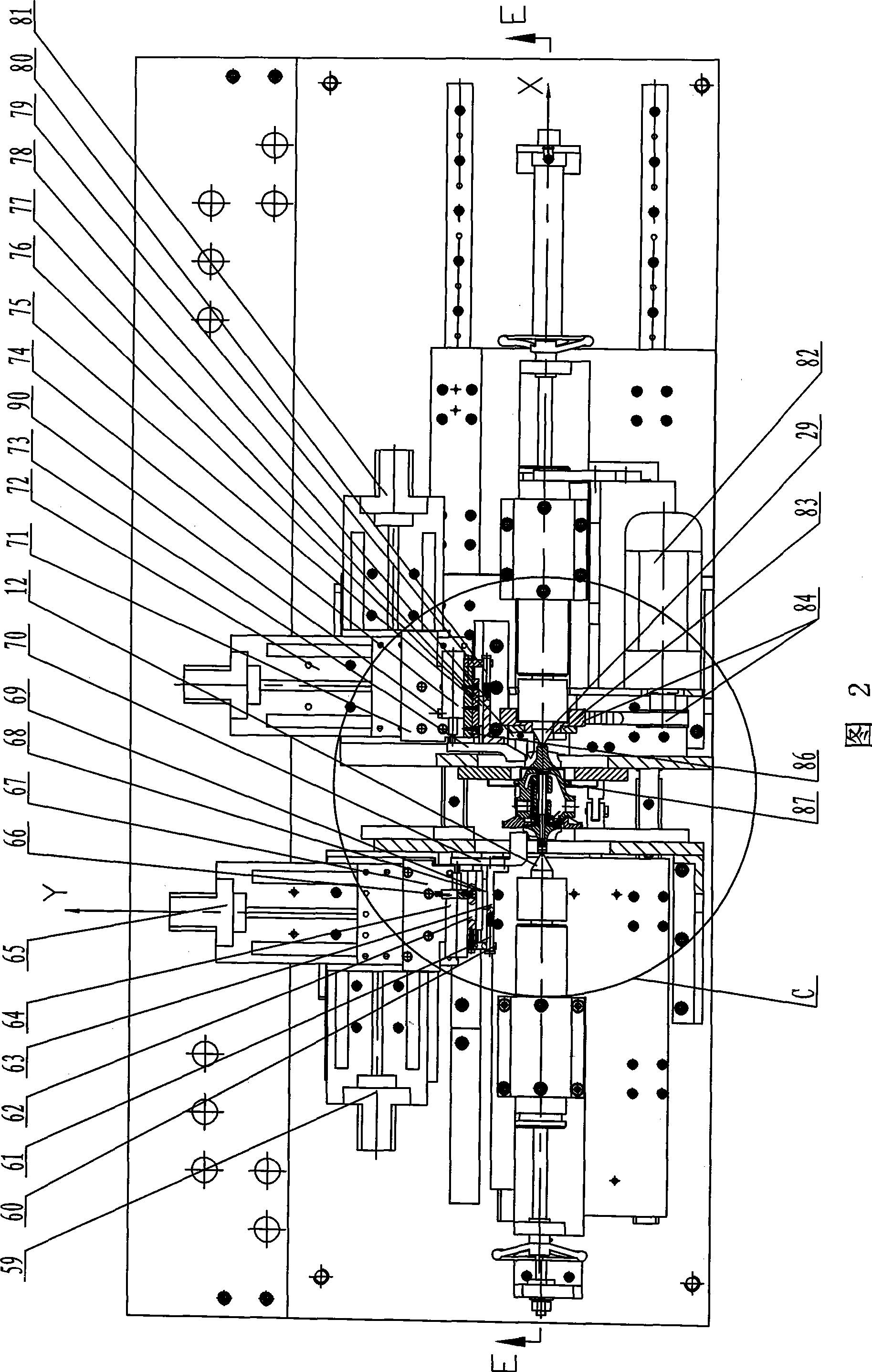
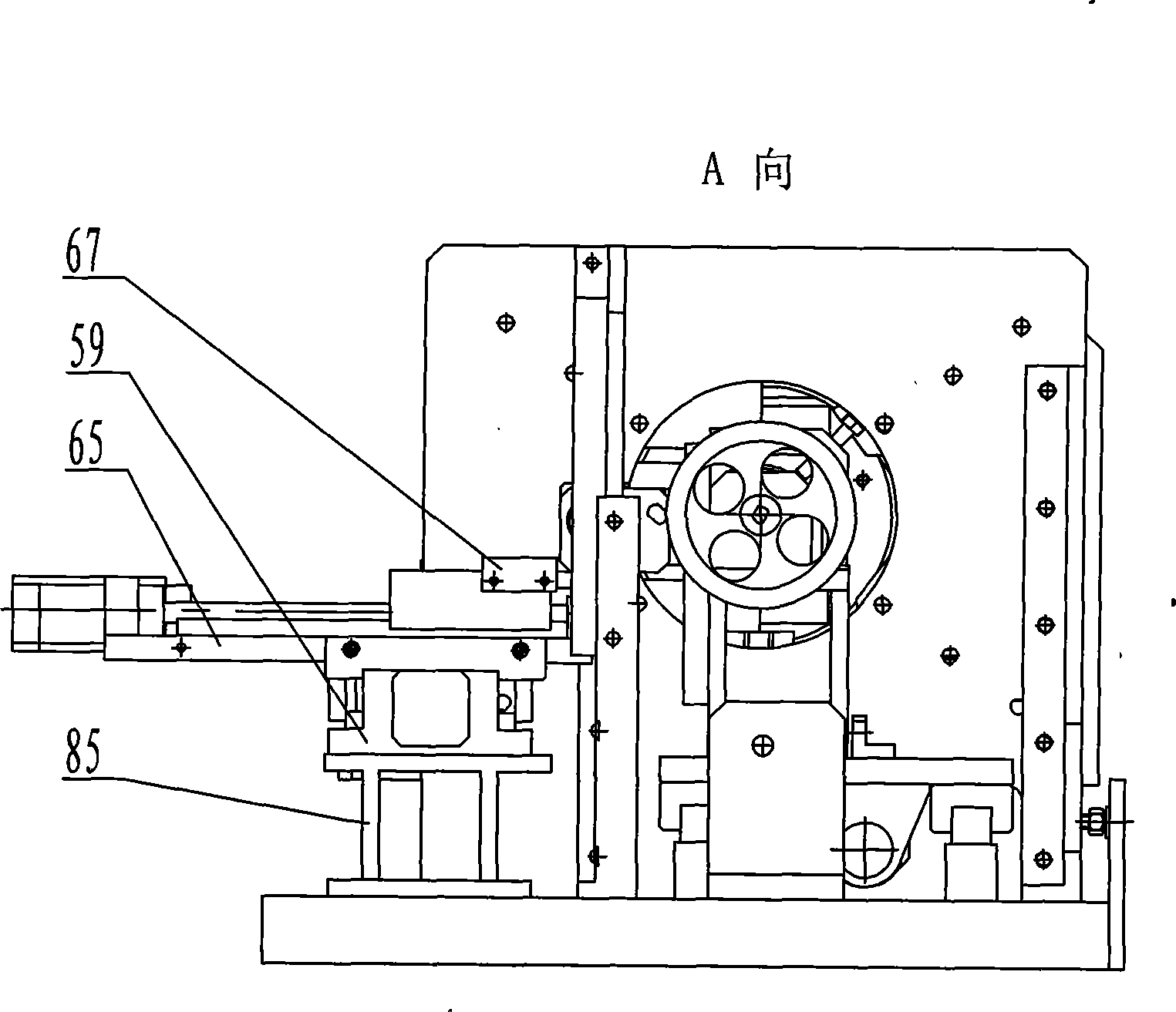
[0007] Specific implementation mode one: in combination with Fig. 1 to Fig. 5 and Figure 8 Describe this embodiment, the measuring device of this embodiment consists of a base 1, an X-to-left linear guide rail 3, an X-to-left slider 4, a left fourth mounting plate 5, a left rotor centering assembly, a left support frame 16, two A left V-shaped positioning block 17, spring 18, adjusting nut 19, screw mandrel left support 20, screw mandrel 21, screw mandrel right support 22, right V-shaped positioning block 23, right guide bar 24, right support frame 25, turn right Sub-centering assembly, motor mounting plate 34, upper linear guide rail 35, upper slider 36, motor support 38, X-right linear guide rail 39, right first mounting plate 40, X-right second slider 41, adjustable Bracket 43, X to the right first slider 44, oil pan 45, right cylinder 47, right second mounting plate 49, positioning head 51, right first bracket 52, left cylinder 54, left guide frame 56, connecting rod 57....

specific Embodiment approach 2

[0008] Specific Embodiment 2: This embodiment is described in conjunction with Fig. 1 and Fig. 5. The left rotor centering assembly of this embodiment consists of a left hand wheel 8, a left bearing seat 9, a left bearing 10, a left lead screw 11, and a left movable top part 12. The left top seat 13, the left lock nut 14 and the left set screw 15 are composed; the left bearing seat 9 is fixedly connected with the left support frame 16, and the inner end of the left lead screw 11 is fixedly connected with the left movable top part 12, The outer end of left screw 11 is fixedly equipped with left hand wheel 8, and left bearing 10 is housed between left bearing block 9 and left screw 11, and left screw 11 and left bearing 10 slide fits, and left top seat 13 is set in the left movable On the top part 12, the left top seat 13 is slidingly matched with the left movable top part 12, the left set screw 15 is mounted on the left top seat 13, and the left lock nut 14 is mounted on the lef...

specific Embodiment approach 3

[0009]Specific Embodiment Three: This embodiment is described in conjunction with Fig. 1 and Fig. 5. The right rotor centering assembly of this embodiment consists of a right set screw 26, a right lock nut 27, a right top seat 28, and a right movable top part 29 , the right lead screw 30, the right bearing seat 31, the right bearing 32 and the right hand wheel 33; The outer end of right leading screw 30 is equipped with right hand wheel 33, and right bearing 32 is housed between right bearing seat 31 and right leading screw 30, and right leading screw 30 and right bearing 32 slide fit, and right top seat 28 suits in the right movable On the top part 29, the right top seat 28 is slidably matched with the right movable top part 29, the right set screw 27 is mounted on the right top seat 28, and the right lock nut 27 is mounted on the right set screw 26. With such arrangement, the structure is simple, and the transmission is stable and reliable. This embodiment is used in combin...


PUM


Abstract

A measuring device for the mounting dimensions of a core rotor of a turbocharger relates to the measuring device for the mounting dimensions of the turbocharger, which aims at the problems that the existing measuring method for the mounting dimensions of the core rotor of the turbocharger has fussy technique, high intensity of worker labor, and low measuring precision, and can not be applicable to the automatically assembling work. A left support frame and a right support frame are fixedly connected with a left V-shaped locating block and a right V-shaped locating block. The centering assembly of a right rotor is fixedly connected with the right support flame. A left cylinder and a right cylinder are both fixedly connected with a base. A positioning head is fixedly arranged on the right cylinder. The left cylinder is connected with a connecting bar, an X direction of which is fixedly connected with a Y directional left accurate electric control terrace part. A left displacement pickup and a right displacement pickup are arranged on a left mounting rack and a light mounting rack. An impeller measuring head is connected with a left third mounting plate, the Y direction of which is fixedly connected with an X directional right accurate electric control terrace part. A turbine measuring head and a shifting fork are fixedly connected with a right first mounting rack. A motor is connected with the shifting fork by a synchronous toothed belt mechanism. The measuring device has the advantages of simple operation, high measuring accuracy (can reach 5 micron), and is suitable for automation assembling work.

Description

technical field [0001] The invention relates to a turbocharger assembly dimension measuring device. Background technique [0002] At present, the method commonly used in the industry to measure the assembly size of the turbocharger core rotor is: before assembling the casing, place a circle of lead wire at the position where the diameter of the impeller (turbine) is measured, assemble the pressure casing (volute), tighten the screws, and then disassemble the pressure casing. Shell (volute), take out the lead wire, measure the thickness of the lead wire with a caliper, and use this value as the assembly clearance. This method has the problems of cumbersome process, high labor intensity of workers, low measurement accuracy and inapplicability to automatic assembly operations. Contents of the invention [0003] The purpose of the present invention is to provide a turbocharger core rotor assembly size measurement device to solve the existing turbocharger core rotor assembly s...

Claims


Application Information

Patent Timeline
Patent Type & Authority Applications(China)
IPC IPC(8): G01B21/10G01B21/16
Inventor 高云峰李瑞峰吕伟新于殿勇
Owner HARBIN INST OF TECH
Why Eureka
Try Eureka