Uncleanness detecting device
A detection method and dirt technology, which is applied in image data processing, television, instruments, etc., can solve problems such as cost increase, achieve low cost, prevent performance degradation, and reduce manpower and effort for maintenance operations
- Summary
- Abstract
- Description
- Claims
- Application Information
AI Technical Summary
Problems solved by technology
Method used
Image
Examples
no. 1 approach
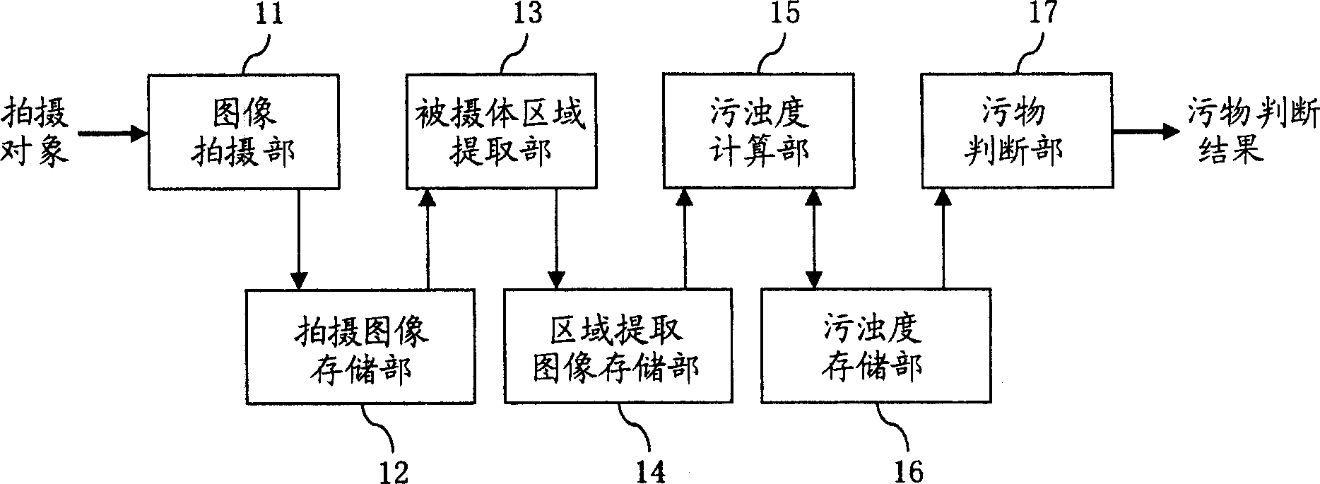
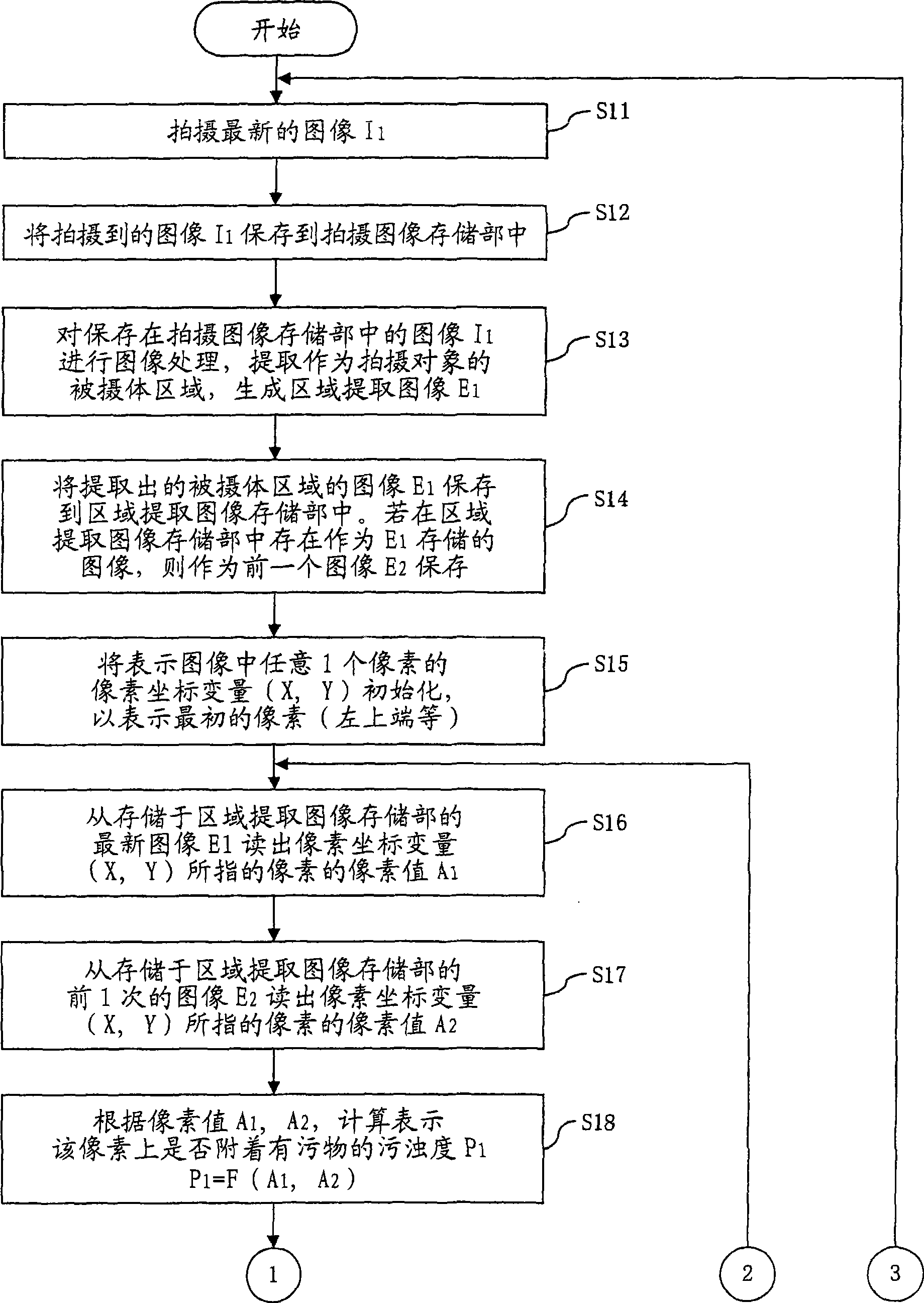
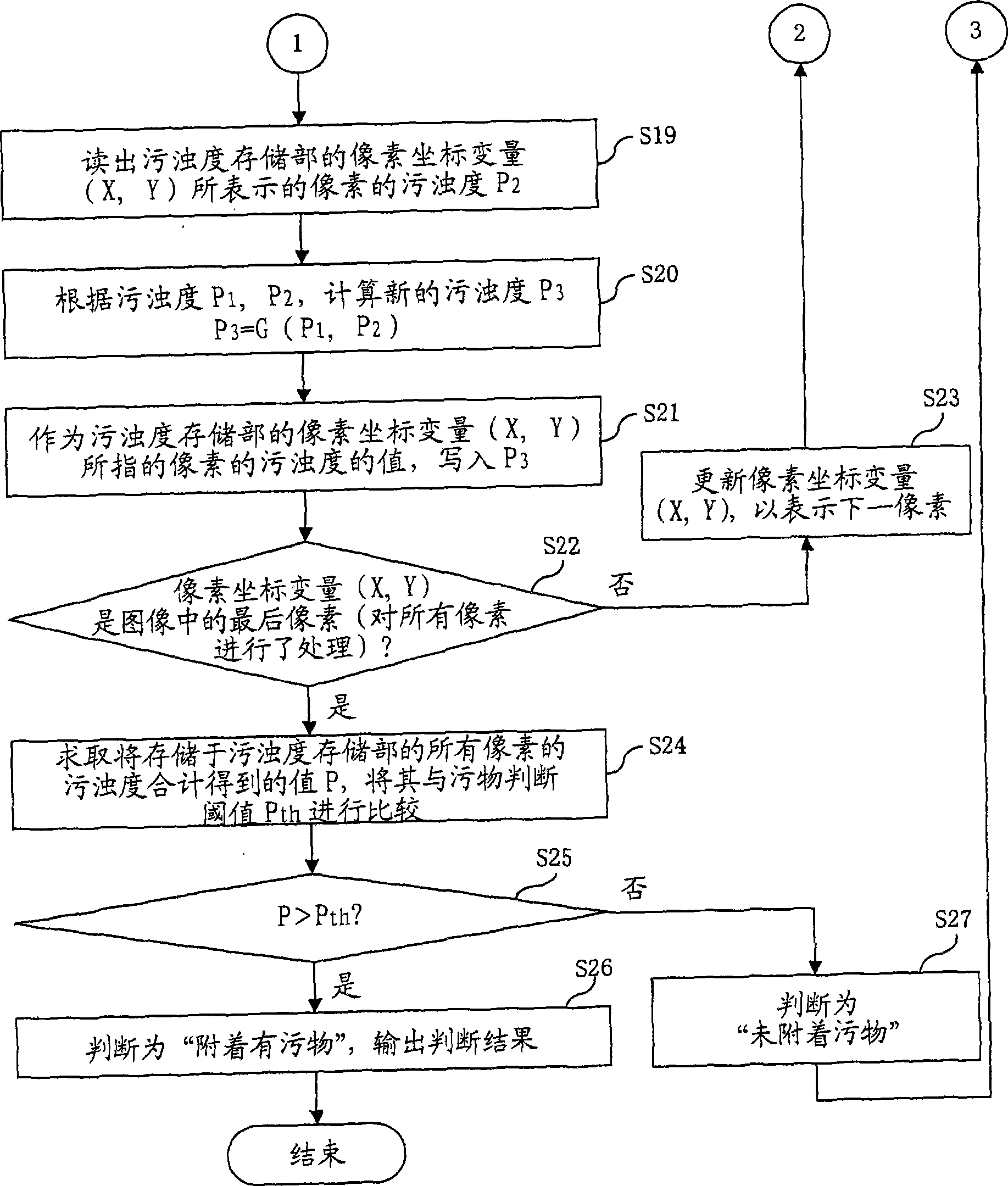
[0036] figure 1 It is a block diagram showing the configuration of the dirt detection system according to the first embodiment of the present invention. figure 1 Among them, the dirt detection method according to the first embodiment of the present invention is composed of the following parts: an image capture unit 11, which is used for monitoring and the like, and is fixed at a fixed point where images can always be continuously captured without installing a movable system; A captured image storage unit 12, which stores the image captured by the image capturing unit 11; a subject area extraction unit 13, which detects that a target subject (such as a vehicle, etc.) is mapped in the captured image stored in the captured image storage unit 12 , extracting the area of the subject to generate an area extraction image; an area extraction image storage unit 14, which stores the latest two or more photographed images obtained by performing area extraction by the subject area extra...
no. 2 approach
[0067] FIG. 11 is a block diagram showing the configuration of a dirt detection system according to a second embodiment of the present invention. In FIG. 11 , the dirt detection method according to the second embodiment of the present invention is composed of the following parts: an image capture unit 21 is used for monitoring, etc., and does not have a movable system, and is fixed at a fixed point where images can be captured continuously at all times. above; the captured image storage unit 22, which stores the image captured by the image capturing unit 21; the subject region extraction unit 23, which detects that a target subject is mapped in the captured image stored in the captured image storage unit 22, and extracts the the region of the subject to generate a region extraction image; the region extraction image storage unit 24 stores the most recent two or more photographed images obtained by region extraction by the subject region extraction unit 23; the region extraction...
no. 3 approach
[0074] Figure 13 It is a block diagram showing the configuration of the dirt detection system according to the third embodiment of the present invention. Figure 13 Among them, the dirt detection method related to the third embodiment of the present invention is composed of the following parts: an image capture unit 31, which is used for monitoring and the like, does not have a movable system, and is fixed at a fixed point that can continuously capture images all the time; An image storage unit 32, which stores the image captured by the image capture unit 31; an object region extraction unit 33, which detects that a target object is mapped in the captured image stored in the captured image storage unit 32, and extracts the captured image; area of the object to generate an area extraction image; the area extraction image storage unit 34 stores a plurality of recent captured images obtained by area extraction by the subject area extraction unit 33 and extracted area mask info...
PUM
 Abstract
Description
Claims
Application Information
 - R&D
- Intellectual Property
- Life Sciences
- Materials
- Tech Scout
- Unparalleled Data Quality
- Higher Quality Content
- 60% Fewer Hallucinations
Browse by: Latest US Patents, China's latest patents, Technical Efficacy Thesaurus, Application Domain, Technology Topic, Popular Technical Reports.
© 2025 PatSnap. All rights reserved.Legal|Privacy policy|Modern Slavery Act Transparency Statement|Sitemap|About US| Contact US: help@patsnap.com


