Brake operation button component of spinning reel

A technology for operating buttons and fishing reels, which is applied in the field of brake operating button assemblies, can solve problems such as deformation of sealing parts

Active Publication Date: 2009-06-24
SHIMANO INC
View PDF1 Cites 6 Cited by
  • Summary
  • Abstract
  • Description
  • Claims
  • Application Information

AI Technical Summary

Problems solved by technology

[0005] However, in the above-mentioned existing structure, for example, when cleaning is performed after putti

Method used


Image

  • Brake operation button component of spinning reel
  • Brake operation button component of spinning reel
  • Brake operation button component of spinning reel

Examples


Embodiment Construction

[0030]

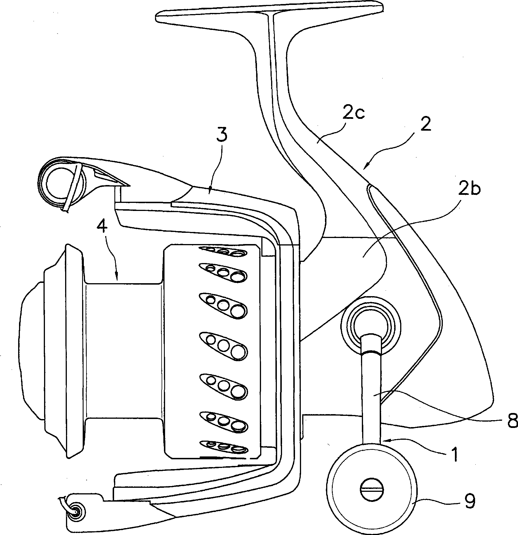
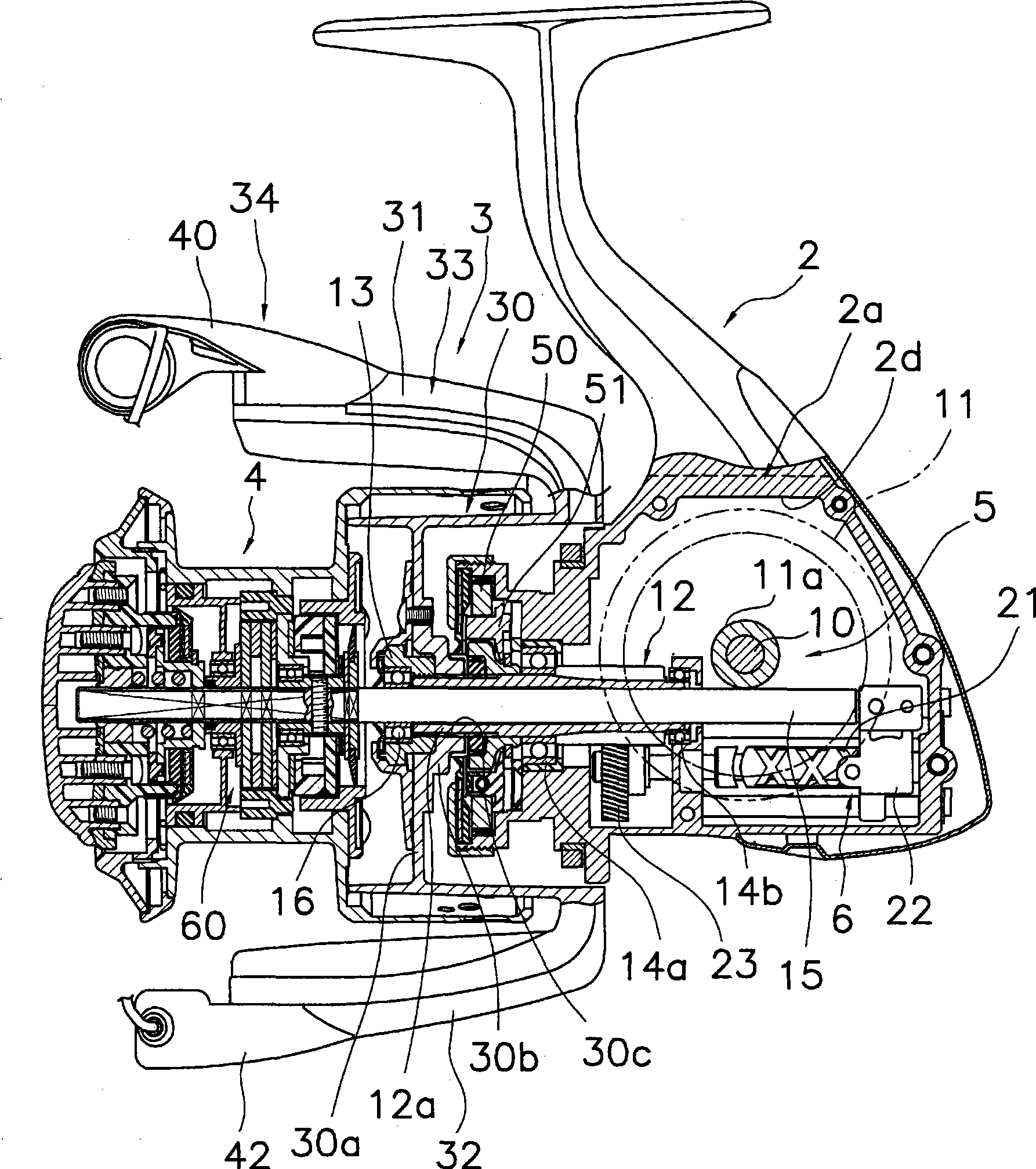
[0031] figure 1 with figure 2 Among them, the spinning fishing reel adopting the first embodiment of the present invention has: a fishing reel main body 2, a rotor 3 and a spool 4, wherein the handle assembly 1 is supported on the fishing reel main body 2, and can be moved relative to the fishing reel The wire wheel main body 2 rotates. The rotor 3 is used to wind the fishing line onto the spool 4 and is mounted on the front portion of the fishing reel main body 2 in a rotatable manner relative to the fishing reel main body 2 . A fishing line is wound on the outer peripheral surface of the spool 4 , which is provided at the front portion of the rotor 3 so as to be movable back and forth. The handle assembly 1 can be installed in figure 1 The left side of the reel body 2 is shown or the right side of the reel body 2 is shown.

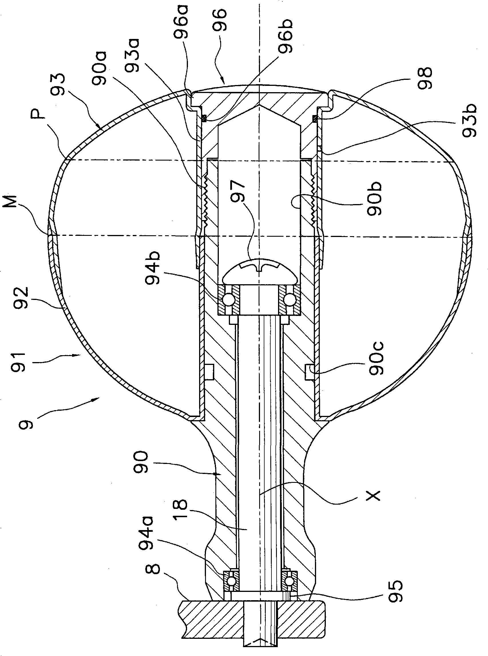
[0032] Such as figure 1 As shown, the handle assembly 1 has a rocker arm 8 and a handle handle 9 , wherein the rocker arm 8 is installed ...


PUM


Abstract

The present invention provide a brake operation knob assembly for spinning type fishing reel, which may prevent liquid from flowing into the brake operation knob assembly even water pressure effects on a sealing member. The brake operation knob assembly includes an operation knob section, a first sealing member and a second sealing member. The operation knob section is used for adjusting brake force and has a first member; a second member rotating relative to the first member and rotation-jointing with a winding reel shaft, and having a protrusion section protruded to be barrel shape towards the first member to cover a cam flange section; a connection section for connecting the first and second members in manner of not moving along axis direction relatively and rotating relatively. The first sealing member is arranged between the winding reel and the first member to seal a gap between the both. The second sealing member is arranged between the first member and the second member to seal a gap between the both, and has a barrel shaped contact section contacting with the periphery surface of the protrusion section of the second member.

Description

technical field [0001] The present invention relates to a brake operating knob assembly, and more particularly to a brake operating knob assembly for a spinning reel that releases fishing line from the front, the brake operating knob assembly being mountable on the spool of a spinning reel reel On the shaft, the braking force generated by the braking friction part and acting on the reel is adjusted. Background technique [0002] In general, the front braking spool of the spinning reel that releases the fishing line from the front is equipped with an unloading mechanism that applies a braking force to the spool. By installing the unloading mechanism, the fishing line will not be easily disconnected even when the fish hook load increases sharply. This force relief mechanism is provided between the spool shaft and the spool, and has a brake operating knob assembly and a brake friction part, wherein the spool is supported on the spool in a rotatable manner relative to the spool...

Claims


Application Information

Patent Timeline
IPC IPC(8): A01K89/027
CPCA01K89/01A01K89/0111A01K89/027
Inventor 北岛启吾
Owner SHIMANO INC
Why Eureka
Try Eureka