

Kinetic energy generation apparatus with improved output power
A technology for generating devices and outputting power, which is applied in the field of kinetic energy generating devices and can solve problems such as low power output efficiency
Inactive Publication Date: 2009-06-24
邱垂南
View PDF3 Cites 0 Cited by
- Summary
- Abstract
- Description
- Claims
- Application Information
AI Technical Summary
Problems solved by technology
Furthermore, the length of the force line 03 is shorter than that of the force line 02, so the force line 02 must provide greater force to maintain the effective output of the transmission shaft 42, so that the power output performance is still low
Method used
View moreImage
Smart ImageViewing Examples

Examples
Embodiment
Login to View More PUM
 Abstract
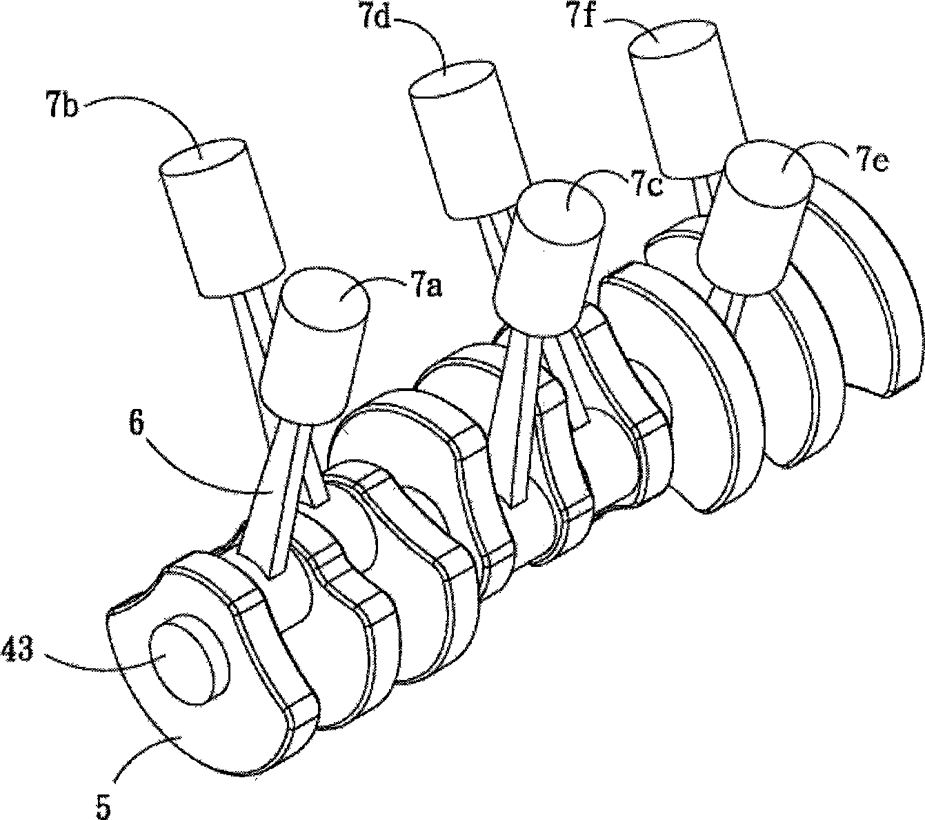
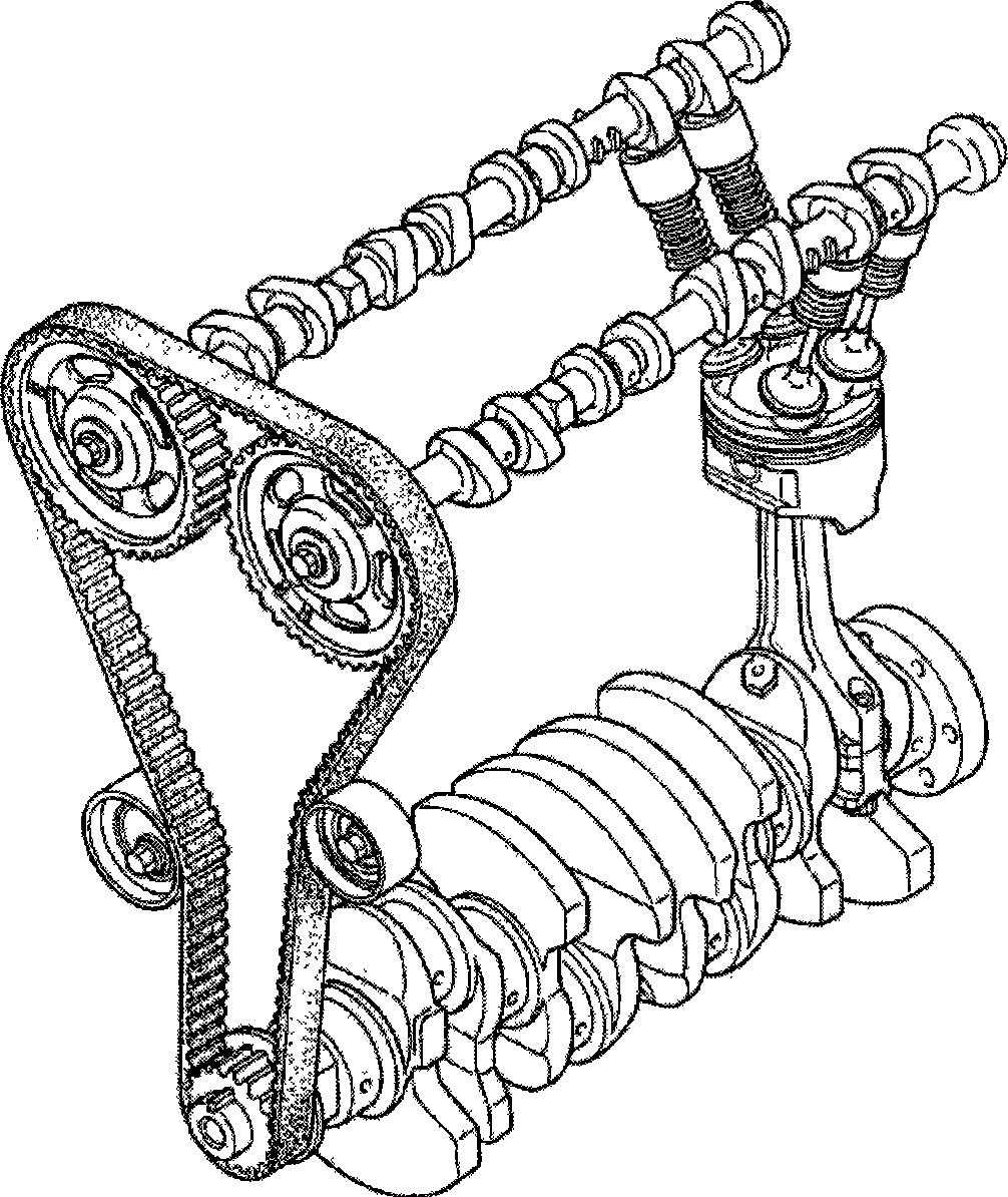
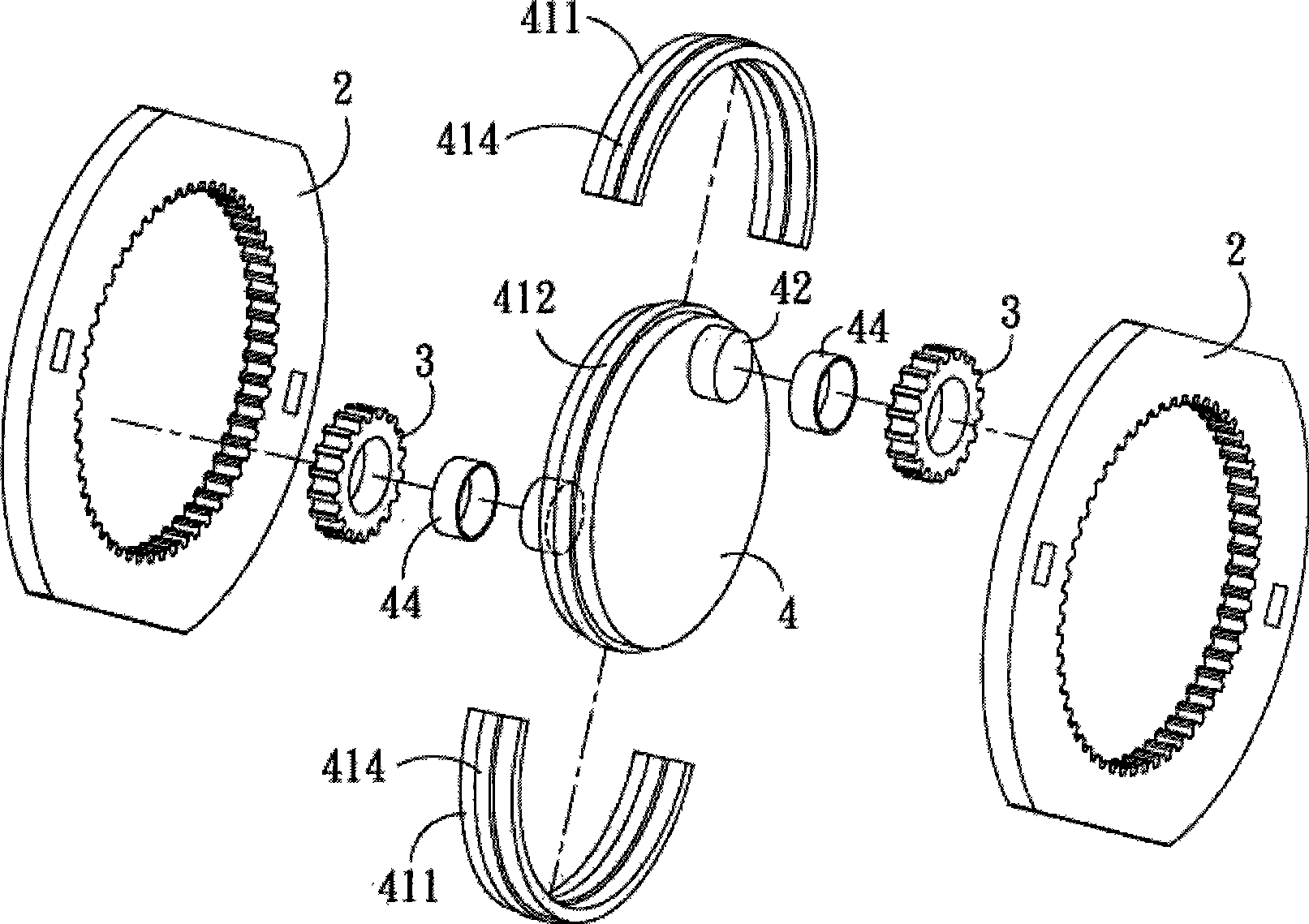
The invention discloses a kinetic energy generating device for improving output power. The device comprises a machine shell; one side of the machine shell is provided with a fixed gear; the gear profile of the fixed gear is inward; correspondingly, the inner side of the fixed gear is provided with a mobile gear; the gear profile of the mobile gear is outward, so that the fixed gear and the mobile gear can mesh and drive mutually; the gear ratio between the fixed gear and the mobile gear is 3:1; of the inner of the machine shell is pivoted with a transmission part; a Bush is arranged between the transmission part and the machine shell; the transmission part is driven to rotate by the mobile gear, and an output axis is extended; the outer side of the transmission gear is fixedly connected with a fly wheel; the fly wheel rotates simultaneously with the mobile gear; one of the fly wheel is provided with a force application axis; the upper axis of the force application axis is provided with a connecting rod; one end of the connecting rod is axially arranged at the force application axis of the fly wheel, and the other end thereof is axially arranged a piston of a cylinder.
Description
technical field The invention relates to a kinetic energy generating device for increasing output power. Background technique The traditional engine operation mode is shown in Figure 23. When the cylinder is burning, the cylinder piston x1 pushes the transmission member x2 to drive the crankshaft x3 to rotate to generate kinetic energy output. But for the transmission part x2, because the movement direction of the transmission part x2 has a relatively large lateral pressure angle, it produces a considerable lateral component force, resulting in the loss of overall kinetic energy; in addition, when the traditional engine is at the top dead center, its The inertial forces of the force point x4 and the crankshaft x3 will cancel each other out, which will not only cause loss of kinetic energy, but also cause vibrations, resulting in damage to the engine and shortening its lifespan. Furthermore, each stroke of a traditional engine must go through four actions: intake air, compr...
Claims
Login to View More Application Information
Patent Timeline
 IPC IPC(8): F01B9/00F01B9/04F02B75/40F02B75/18F16H37/12
Inventor邱垂南
Owner邱垂南